
Technical data


15
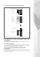
5.7.2 fuses (contd)
Fuses 1 and 2 protect the power supply phase and neutral. Fuse 3 protects the entire 24V AC circuit.
The 24V AC power supply is rectified in the boiler control panel and controls the fan and supplies the room
unit(s) with voltage. The supply voltage of the sensors is not accessibly fused in the boiler control panel.
This applies also for the protection of the ignition transformer. In the case of a fault in these areas, the
boiler control panel must be replaced.
5.7.3 connecting a boiler (transport) pump
It is recommended that the boiler pump be electrically connected to the boiler. The pump will start as
dictated by the boiler, will overrun when necessary and will run when commanded by the boiler's own frost
protection programme.
The signal to start the pump is provided via plug x 33 and where the pump motor does not exceed 600
watts, 230V 1 phase, the pump may be driven directly from power available from the boiler inbuilt controls,
plug x 33 is located on a flying lead and may be found in the top area of the boiler approximately half way
along the length of the boiler. Where the pump motor exceeds 600watts an auxillary relay must be used.
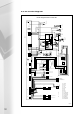
5.7.4 external temperature sensor
Where weather variable/direct on boiler weather compensation control is required, the external
temperature sensor must be installed. The external sensor should be mounted on the North or Northeast
side of the buildings, at approximately 2/3 of façade height.
The external temperature sensor should not be mounted above windows or below eaves. Under no
circumstances may the sensor be exposed to direct sunlight. The external temperature sensor should be
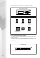
connected via two cores on plug No 4 – see fig 5.7b.
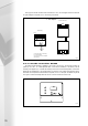
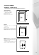
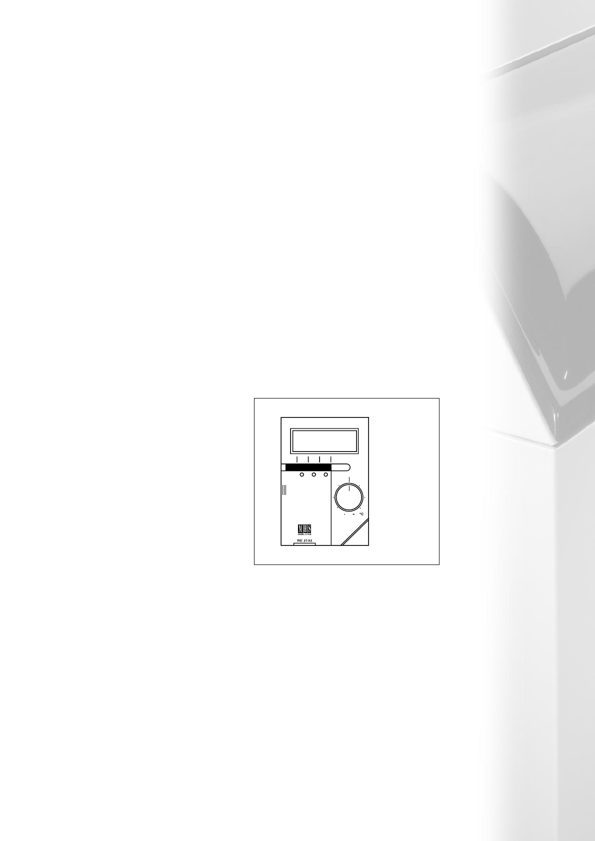
5.7.5 room unit RE 2132
Where room temperature influence, or
remote adjustment is required, a room unit will
need to be installed. This is available as an
additional accessory (see fig 5.7d).
If the room temperature sensor of the room
unit is used, no thermostat/radiator/convector
valves should be installed in the room with the
room unit.
The room unit must not be directly influenced
by insulation or heat sources, such as heat emitters
or direct sunlight. The room unit should be
connected via three cores on plug No 4 –
see fig 5.7b.
5.7.6 external on/off control
Where this is required a 230V AC volt-free contact must be installed. With the contact open, the
boiler control is switched to the frost protection function, whilst with the contact closed, depending on the
DIP switch configuration of the boiler control, the boiler will operate.
The external on/off control should be connected via two cores on plug (3), terminals L1 and L2, fig
5.7b. Only one of the aforementioned control systems can be utilised at one time.
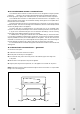
Fig 5.7d
Remote tamper
proof temperature
sensors are
available to allow
the controller to
be installed in a
non heated area
Sensor ID
= QAW44