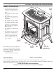
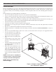
DIRECT VENT GAS STOVE CSDV20SNV CSDV20DNV CSDV20SLP CSDV20DLP MODELS: CSDV30SNV CSDV30DNV CSDV30SLP CSDV30DLP CSDV40SNV CSDV40DNV CSDV40SLP CSDV40DLP INSTALLATION AND OPERATING INSTRUCTIONS ON WARNINGS OFF IF THE INFORMATION IN THESE INSTRUCTIONS ARE NOT FOLLOWED EXACTLY, A FIRE OR EXPLOSION MAY RESULT CAUSING PROPERTY DAMAGE, PERSONAL INJURY OR LOSS OF LIFE. – Do not store or use gasoline or other flammable vapors and liquids in the vicinity of this or any other appliance.
CONTENTS CONGRATULATIONS! You have purchased a state-of-the-art gas appliance featuring the Lex-Fire Burn System available exclusively on Lexington Forge gas appliances. The Lex-Fire Burn System sets a new standard for flame appearance through innovative log design, burner technology and ember placement. Each element effecting combustion and flame appearance was carefully scrutinized and strategically balanced during the design process to provide a product that was truly “BORN TO BURN.
IMPORTANT SAFETY INFORMATION WARNING INSTALLER Please leave these instructions with the appliance. OWNER Please retain these instructions for future reference. • Read this owner’s manual carefully and completely before trying to assemble, operate, or service this stove. • Any change to this stove or its controls can be dangerous. • Improper installation or use of this stove can cause serious injury or death from fire, burns, explosions, electrical shock and carbon monoxide poisoning.
IMPORTANT SAFETY INFORMATION 13. Never place anything on top of stove. 17. When the appliance is installed directly on carpeting, tile or other combustible material other than wood flooring, you must set appliance on a metal or wood panel or hearth pad extending the full width and depth of the appliance. 14. Do not use any solid fuels (wood, coal, paper, cardboard, etc.) in this stove. Use only the gas type indicated on burner system nameplate. 18.
PRODUCT FEATURES AND CODE APPROVAL PRODUCT SPECIFICATIONS • This appliance has been certified for use with either natural or propane gas. See appropriate data plates. • This appliance is not for use with solid fuels. • The appliance is approved for bedroom or bedsitting room installations. • The appliance must be installed in accordance with local codes if any. If none exist use the current installation code. ANSI Z223.1/ NFPA 54 in the USA, CAN/CGA B149 in Canada.
PRE-INSTALLATION INFORMATION INSTALLING ABOVE 2000 FEET • In the USA, the appliance must be derated 4% for every 1,000 ft above 2,000 ft elevations. • In Canada, these appliances are certified for altitudes of 0 – 2000 ft, and must be de-rated by 10 percent for installations between 2000 and 4,500 ft. (derate an additional 4% for every 1,000 ft. above 4,500 ft. elevations). ORIFICE SIZES, PRESSURES AND BTUs NATURAL GAS Manifold Press: (W.C.) 3.5" Maximum Supply Pressure 10.5" Minimum Supply Pressure 4.
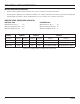
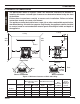
PRE-INSTALLATION INFORMATION STOVE DIMENSIONS A B C DV20 207/8" 231/2" 183/4" DV30 261/2" 281/2" 21" DV40 291/2" 301/2" 22" A C B Figure 2 - External Stove Dimensions 58D6056 7
PRE-INSTALLATION INFORMATION STOVE LOCATION Plan for the installation of your stove. This includes determining where the unit is to be installed, the vent configuration to be used, framing and finishing details, and whether any optional accessories (i.e. blower, wall switch, or remote control) are desired. Consult your local building code agency to ensure compliance with local codes, including permits and inspections.
CLEARANCES CLEARANCES TO COMBUSTIBLES WARNING The dimensions shown in Figures 4 and 5 are minimum clearances to maintain in installing this heater. Left and right clearances are determined when facing the front of the heater. Follow these instructions carefully to ensure safe installation. Failure to follow instructions exactly can create a fire hazard. The appliance cannot be installed on a carpet, tile or other combustible material other than wood flooring.
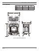
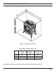
CLEARANCES / HEIGHT REQUIREMENTS C B ON OFF A Figure 5 - Placing Stove in Alcove Tested Minimum Alcove Dimensions DV20 DV30 Height From Hearth A 52" 64" Width B 30" 35" Depth C 36" 36" DV40 64" 35" 36" Note: Maintain minimum side and back clearances when placing stove in alcove.
REMOVING UNIT FROM CRATE 1. Remove two (2) straps. See Figure 6. 2. Open plastic bag and slide to bottom of unit. See Figure 7. 3. Lift up on ash lip and pivot down to open control door. See Figure 8. 4. Lift up on front. Pivot bottom of front out. Remove front. See Figure 8. 5. Open and remove glass door. 6. Remove log box from inside of unit. 7. Lift unit off pallet. Lift unit up high enough to clear upright supports unit is sitting on.
Read all instructions completely and thoroughly before attempting installation. Failure to do so could result in serious injury, property damage or loss of life. Operation of improperly installed and maintained venting system could result in serious injury, property damage or loss of life. NOTICE WARNING VENT INSTALLATION Failure to follow these instructions will void the warranty. INSTALLATION PRECAUTIONS Consult local building codes before beginning the installation.
VENT INSTALLATION INSTALLATION PLANNING There are two basic types of direct-vent installation: • Horizontal Termination • Vertical Termination It is important to select the proper length of vent pipe for the type of termination you choose. It is also important to note the wall thickness. Select the amount of vertical rise desired. The horizontal run of venting must have 1/4" rise for every 12" of run towards the termination. You may use up to three 90° elbows in this vent configuration.
VENT INSTALLATION FOR HORIZONTAL TERMINATION Inside Corner Detail G V H A D E C B B G B V L F Fixed Closed Operable B I Opera- Fixed ble Closed V V V B A V Vent Terminal A V A M B V J Air Supply Inlet A K A Area Where Terminals Not Permitted Figure 9 - Horizontal Vent Termination Location MINIMUM DISTANCES A = Clearance above the grade, a veranda, porch, deck, or balcony [*12" (305mm) minimum]. B = Clearance to window or door that may be opened [*12" (305mm) minimum].
VENT INSTALLATION TERMINATION CLEARANCES FOR BUILDINGS WITH COMBUSTIBLE AND NONCOMBUSTIBLE EXTERIORS D C C G G=6" (152mm) V V V Inside Corner Outside Corner H G V V J G = Combustible 24"(610mm) Noncombustible 18"(457mm) Balcony with No Side Wall E F=6" (152mm) F Combustible & Noncombustible H = 24" (610mm) J = 20" (508mm) C = Maximum depth of 48" (1219mm) for alcove location D = Minimum width for back wall of alcove location Combustible - 38" (965mm) Noncombustible - 24" (610mm) E = Cleara
VENT INSTALLATION 1. Determine the route your horizontal venting will take. Note: The location of the horizontal vent termination on the exterior wall must meet all local and national building codes. Snorkel terminations are available for terminations requiring a vertical rise on the exterior of the building. See Figures 12 and 13. Follow the same installation procedures used for standard horizontal terminations.
VENT INSTALLATION HORIZONTAL VENT INSTALLATION (continued) 3. Attach vent pipe assembly to the stove. Set stove in front of its permanent location to insure minimum clearances. Mark the wall for a 91/2" (241) square hole (for noncombustible material such as masonry block or concrete, a 71/2" [190mm] diameter hole is acceptable). See Figure 15. The center of the hole should line up with the center line of the horizontal rigid vent pipe.
VENT INSTALLATION HORIZONTAL VENT INSTALLATION (continued) Interior Wall Surface 5. Slide the wall thimble over the vent pipe before connecting the horizontal run to the vent cap. See Figure 18. 6. Carefully move the stove with vent assembly attached toward the wall and insert the vent pipe into the horizontal termination. The pipe overlap should be a minimum of 11/4" (mm). Apply silicone to the outer pipe connection. Fasten all vent connections with screws provided. 7.
VENT INSTALLATION VENTING WITH TWO 90° ELBOWS H1 NOTE: Add 1/4" rise per 12" horizontal length of pipe. Maximum Horizontal (H) Vertical Minimum CSDV20 (V) Vertical Minimum CSDV30 (V) H Vertical Minimum CSDV40 (V) 2' 41.50" 52.50" 54.50" 20' 95.25" 98.75" 102.25" V Table 2 - Venting with Two 90° Elbows Figure 20 - Horizontal Termination Configuration for Rigid Venting Using Two 90° Elbows VENTING WITH THREE 90° ELBOWS NOTE: Add 1/4" rise per 12" horizontal length of pipe.
VENT INSTALLATION INSTALLATION FOR VERTICAL TERMINATION 1. Determine the route your vertical venting will take. If ceiling joist, roof rafters or other framing will obstruct the venting system, consider an offset. See Figure 22 to avoid cutting load bearing members. NOTE: Pay special attention to these installation instructions for required clearances (air space) to combustibles when passing through ceilings, walls, roofs, enclosures, attic rafters, etc. Do not pack air spaces with insulation.
VENT INSTALLATION 4. Connect a section of pipe and extend up through the hole. NOTE: If an offset is needed to avoid obstructions, you must support the vent pipe every three (3) feet. Use wall straps for this purpose. See Figure 22, page 20. Whenever possible, use 45° elbows instead of 90° elbows. The 45° elbow offers less restriction to the flow of the flue gases and intake air. 5. Place the flashing over the pipe section(s) extending through the roof.
VENT INSTALLATION VERTICAL TERMINATION CONFIGURATIONS Figures 27 through 30 on pages 22 and 23 show four different configurations for vertical termination. IMPORTANT: Install restrictor as indicated on chart (Figure 11) on page 15. NOTE: Install restrictor into 4" collar of stove or first vent section as shown. Maximum Horizontal (H) Vertical Minimum CSDV20 (V) Vertical Minimum CSDV30 (V) Vertical Minimum CSDV40 (V) 2' 41.50" 52.50" 54.50" 20' 95.25" 98.75" 102.
VENT INSTALLATION H Maximum Horizontal (H) Vertical (V+V1) Minimum CSDV20 (V) Vertical (V+V1) Minimum CSDV30 (V) Vertical (V+V1) Minimum CSDV40 (V) 2' 41.25" 44.75" 48.75" 20' 95.25" 98.75" 102.25" Table 7 - Venting with Two 90° Elbows NOTE: Vertical (V) + Vertical (V1) = 20' Maximum V1 V NOTE: Install restrictor into 4" collar of stove or front vent section as shown.
STOVE INSTALLATION CHECK GAS TYPE Use proper gas type for the burner system you are installing. If you have conflicting gas type, do not install burner system. See dealer where you purchased the stove and burner system for proper burner system according to your gas type. CAUTION WARNING INSTALLING GAS PIPING TO STOVE / BURNER SYSTEM LOCATION A qualified installer or service person must connect appliance to gas supply. Follow all local codes.
Only persons licensed to work with gas piping may make the necessary gas connections to this appliance. CAUTION WARNING STOVE INSTALLATION A manual shutoff valve must be installed upstream of the appliance. Union tee and plugged 1/8" NPT pressure tapping point should be installed upstream of the appliance. See Figure 32. NOTE : The gas line connection may be made using 1/2" rigid tubing or an approved flex connector.
CHECKING GAS PRESSURE Check gas type. The gas supply must be the same as stated on the appliance’s rating decal. If the gas supply is different from the fireplace, STOP! Do not install the appliance. Contact your dealer immediately. 2. To ease installation, a 30" (mm) flex line with manual shut-off valve has been provided with on this appliance. Install and attach 1/2" gas line onto shut-off valve. 3.
ELECTRICAL INSTALLATION ELECTRICAL WIRING This stove will work without any electrical supply. Electricity is only needed if you install a remote wall mounted switch. WARNING Electrical connections should only be performed by a qualified, licensed electrician. Main power must be off when connecting to main electrical power supply or performing service. All wiring shall be in compliance with all local, city, and state codes.
LOG PLACEMENT AND ROCK WOOL PLACEMENT WARNING Before you begin — This unit is supplied with ceramic fiber logs. Do not handle these logs with your bare hands. Always wear gloves to prevent skin irritation from ceramic fibers. After handling the logs, wash your hands gently with soap and water to remove any traces of fibers. The positioning of the logs is critical to the safe and clean operation of this heater.
LOG PLACEMENT AND ROCK WOOL PLACEMENT INSTALLING CSDV30 LOGS IN FIREBOX (See Figure 37) 1. Carefully remove logs from wrapping. 2. Open front door of firebox. 3. Place rear log (#1) on rear log pin. 4. Place left base log (#2) on the two pins against left side of firebox. 5. Place right base log (#3) on the two pins against right side of firebox. 6. Place top left log (#4) on left base log. Line up the notch in the bottom of the top log with the locator pins on the bottom log. 7.
LOG PLACEMENT AND ROCK WOOL PLACEMENT INSTALLING CSDV40 LOGS IN FIREBOX (See Figure 39) 1. Carefully remove logs from wrapping. 2. Open front door of firebox. 3. Place rear log (#1) on rear log pins. 4. Place left base log (#2) on the two pins against left side of firebox. 5. Place right base log (#3) on the two pins against right side of firebox. 6. Place top left log (#4) on left base log. Line up the notch in the bottom of the top log with the locator pins on the bottom log. 7.
OPERATING INSTRUCTIONS WARNING FOR YOUR SAFETY READ BEFORE LIGHTING If you do not follow these instruction exactly, a fire or explosion may result causing property damage, personal injury or loss of life. A. This appliance is equipped with an pilot which must be lit by hand while following these instructions exactly. B. BEFORE OPERATING smell all around the appliance area for gas. Be sure to smell next to the floor because some gas is heavier than air and will settle on the floor.
OPERATING INSTRUCTIONS T LIGHTING PILOT FOR THE FIRST TIME WARNING INITIAL LIGHTING Purge air from the supply line as follows: • Unscrew main pressure test point. • Leave inlet test screw open until gas comes in. • When gas is flowing, tighten inlet screw immediately.
OPERATING INSTRUCTIONS T LIGHTING BURNER MAIN BURNER SWITCH The “ON/OFF” switch for the main burner can be found on the back right side of the stove. This switch allows you to turn on and to turn off the main burner without using the gas valve knob. Make sure the button is in the “ON” position to light the main burner. See Figure 42. ON F OF Figure 42 - Burner Switch LIGHTING THE BURNER Depress and turn the knob counterclockwise to the “ON” position. See Figure 43.
CLEANING AND MAINTENANCE VENTING SYSTEM A qualified agency should examine the venting system annually. CLEANING GLASS CAUTION Make sure the gas valve knob is in the “OFF” position. Wait at least five (5) minutes before start ing maintenance. Let glass cool before cleaning. Do not clean glass when it is hot. Damage could occur. Clean the ceramic glass periodically. Condensation will sometimes form on the glass during a cold startup. This is normal for all gas fireplaces and stoves.
AIR SHUTTER ADJUSTMENT (NATURAL GAS ONLY) ADJUSTING THE AIR SHUTTER The venturi of the burner is equipped with an air shutter. The opening of the venturi has been set at 1/4" for Natural Gas and fully open for Propane installation at sea level. Natural Gas Models may be adjusted for high altitude as follows: • To increase air mixture, pull down the adjustment rod located beneath the stove. This opens the shutter more and will stop sooting. See Figure 49.
Always use gloves when handling broken glass. WARNING CAUTION GLASS REPLACEMENT Make sure the glass panel edges do not touch any metal parts during thermal expansion. 1. Put on gloves. 2. Remove door from stove. See Page 11. 3. Remove glass from stove by releasing two clamps on bottom of stove. Lift glass frame up and off the unit. See Figure 51. 4. Carefully remove broken glass. 5. Wrap new glass pane with tadpole gasket. Make sure you have 1/4" overlap on each side. 6. Place new glass in frame. 7.
REPLACEMENT PARTS CSDV20 20 18 17 7 14 9 19 6 16 15 1 11 2 10 8 12 5 3 13 4 58D6056 37
REPLACEMENT PARTS REPLACEMENT PARTS ARE AVAILABLE THROUGH YOUR RETAILER CSDV20 Item Description Qty Natural Propane 1 Burner Assembly 1 58D0250 58D0250 2 Log Support Bracket 1 58D0210 58D0210 3 Pilot Assembly 1 37D0018 37D0019 4 SIT 820 Nova Valve 1 37D0117 37D0118 5 Injector 1 62D3006 20H3146 6 Venturi 1 45D0600 45D0600 7 Valve Tube 1 58D0163 58D0163 8 ON/OFF Rocker Switch 1 41D0048 41D0048 9 Ceramic Glass 1 58D0207 58D0207 10 Air Shutter Rod 1 58D0048 5
REPLACEMENT PARTS CSDV30 17 22 7 18 15 8 21 20 16 6 9 19 1 5 10 2 11 14 12 3 13 4 58D6056 39
REPLACEMENT PARTS REPLACEMENT PARTS ARE AVAILABLE THROUGH YOUR RETAILER CSDV30 Item Description Qty Natural Propane 1 Burner Assembly 1 58D0150 58D0150 2 Log Support Bracket 1 58D0024 58D0024 3 Pilot Assembly 1 37D0018 37D0019 4 SIT 820 Nova Valve 1 37D0117 37D0118 5 Injector 1 58D0102 20H3144 6 Venturi 1 45D0600 45D0600 7 Valve Tube 1 58D0163 58D0163 8 ON/OFF Rocker Switch 1 41D0048 41D0048 9 Ceramic Glass 1 58D0028 58D0028 10 Air Shutter Rod 1 58D0048 5
REPLACEMENT PARTS CSDV40 25 22 26 24 23 28 8 19 20 18 10 2 15 11 3 12 2 7 9 6 17 13 21 4 14 16 5 58D6056 41
REPLACEMENT PARTS REPLACEMENT PARTS ARE AVAILABLE THROUGH YOUR RETAILER CSDV40 Item Description Qty Natural Propane 1 Burner Assembly 1 58D0368 58D0368 2 Rear Burner Assembly 1 58D0362 58D0362 3 Log Support Bracket 1 58D0310 58D0310 4 Pilot Assembly 1 20H2048 20H2049 5 SIT 820 Nova Valve 1 37D0117 37D0118 6 Front Injector 1 20H3150 20H3151 7 Rear Injector 1 62D3006 33D4046 8 Venturi 1 45D0600 45D0600 9 ON/OFF Rocker Switch 1 41D0048 41D0048 10 Ceramic Glass
WARNING WARNING TROUBLESHOOTING Turn appliance OFF and allow to cool before servicing. Only a qualified service person should service and repair the heater. Note: All troubleshooting items are listed in order of operation. OBSERVED PROBLEM POSSIBLE CAUSE REMEDY Spark ignitor will not light 1. Battery needs replacing the pilot after repeated press- 2. Defective ignitor ing of spark ignitor. 1. Replace battery 2. Check connections to ignitor.
INSTALLATION RECORDS THE FOLLOWING INFORMATION MUST BE RECORDED BY THE INSTALLER FOR WARRANTY PURPOSES AND FUTURE REFERENCE. LEXINGTON FORGE Model: _____________________________ Name of Owner: Name of Installer: Address: Address: Phone: Phone: Name of Dealer: Address: Phone: Manufactured by LEXINGTON FORGE 149 Cleveland Drive Paris, Kentucky 40361, U.S.A.
MASSACHUSETTS RESIDENTS ONLY: PLEASE READ AND FOLLOW THESE SPECIAL REQUIREMENTS NOTE REGARDING VENTED PRODUCTS This product must be installed by a licensed plumber or gas fitter when installed within the Commonwealth of Massachusetts. Any residence with a direct vent product must have a CO detector installed in the residence. Installation of the fireplace or vented gas log in the State of Massachusetts requires the damper to be permanently removed or welded in the fully open position.
SPECIAL REQUIREMENTS CONTINUED 2. APPROVED CARBON MONOXIDE DETECTORS. Each carbon monoxide detector as required in accordance with the above provisions shall comply with NFPA 720 and be ANSI/UL 2034 listed and IAS certified. 3. SIGNAGE. A metal or plastic identification plate shall be permanently mounted to the exterior of the building at a minimum height of eight (8) feet above grade directly in line with the exhaust vent terminal for the horizontally vented gas fueled heating appliance or equipment.
NOTES 58D6056 47
WARRANTY COVERAGE Lexington Forge warrants its products to be free of defects in material and workmanship and backs each product with a Limited Lifetime Warranty. This warranty is to the original purchaser of a Lexington Forge product and is not transferable. LIFETIME WARRANTY Covered under this warranty are the stove body, combustion chamber, door frame, gold plating (manufacturing defects only), glass (thermal breakage only), heat exchange system, and burner.