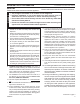
ON F OF Unvented Gas Cast Iron Stove Installation & Operating Instructions Single Door Models: CSVF20SNV CSVF30SNV CSVF20SPV CSVF30SPV Double Door Models: VFCS20DNV VFCS30DNV VFCS20DPV VFCS30DPV WARNINGS If the information in this manual is not followed exactly, a fire or explosion may result causing property damage, personal injury or loss of life. – Do not store or use gasoline or other flammable vapors and liquids in the vicinity of this or any other appliance.
Unvented Cast Iron Gas Stoves CONTENTS PLEASE READ THE INSTALLATION & OPERATING INSTRUCTIONS BEFORE USING APPLIANCE. Thank you and congratulations on your purchase of an MHSC stove. IMPORTANT: Read all instructions and warnings carefully before starting installation. Failure to follow these instructions may result in a possible fire hazard and will void the warranty. Important Safety Information..................................... 3 Product Features.......................................................
Unvented Cast Iron Gas Stoves IMPORTANT SAFETY INFORMATION OWNER Please leave these instructions with the appliance. Please retain these instructions for future reference. WARNING INSTALLER • Any change to this heater or its controls can be dangerous. • Improper installation or use of the heater can cause serious injury or death from fire, burns, explosion or carbon monoxide poisoning. • Do not allow fans to blow directly into the stove. Avoid any drafts that alter burner flame patterns.
Unvented Cast Iron Gas Stoves IMPORTANT SAFETY INFORMATION Continued from page 3 20. 21. 22. 23. 24. 25. 26. The initial break-in operation should last two to three hours with the burner at the highest setting. Provide maximum ventilation by opening windows or doors to allow odors to dissipate. Any odors remaining after this initial break-in period will be slight and will disappear with continued use. Input ratings are shown in BTU per hour and are for elevations up to 2,000 feet.
Unvented Cast Iron Gas Stoves product features On/Off Switch ON F OF ON F OF Handle On/Off Switch Break-Away Handle Optional Remote Receiver Optional Remote Receiver Piezo ST1164 Hi/Lo Knob Hi/Lo Knob Off/Pilot/On Knob Fan Switch Off/Pilot/On Knob Optional Fan Switch Door Figure 1 Cast Iron Stove (Single Door) Figure 2 Cast Iron Stove (Double Door) Natural Propane (LP) CSVF controls Regulator Pressure 3.5” w.c. 10.0” w.c. Pilot Regulator 3.5” w.c. n/a Max. Gas Inlet Pressure 10.5” w.c.
Unvented Cast Iron Gas Stoves dimensions A C B Figure 3 Stove Dimensions Ref.
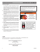
Unvented Cast Iron Gas Stoves GETTING STARTED CAUTION Gloves are recommended when handling ceramic fiber logs to prevent skin irritation from loose fibers. Logs are fragile — handle with care. AVAILABLE COLORS G EBL ES EMB Graphite Enamel Black Enamel Sand Enamel Brown Make sure you have received all parts: Check your packing list to verify that all listed parts have been received.
Unvented Cast Iron Gas Stoves COMBUSTION and VENTILATION AIR ADEQUATE COMBUSTION AND VENTILATION AIR This heater shall not be installed in a confined space or unusually tight construction unless provisions are provided for adequate combustion and ventilation air. The National Fuel Gas Code, (ANSI Z223.1/NFPA54), defines a confined space as a space whose volume is less than 50 cubic feet per 1,000 BTU per hour (4.
Unvented Cast Iron Gas Stoves WARNING CLEARANCES and HEIGHT REQUIREMENTS The dimensions shown in Figure 5 are minimum clearances to maintain in installing this heater. Left and right clearances are determined when facing the front of the heater. Follow these instructions carefully to ensure safe installation. Failure to follow instructions exactly can create a fire hazard.
Unvented Cast Iron Gas Stoves CLEARANCES and HEIGHT REQUIREMENTS C B ON OFF A ST1171 Figure 6 Alcove Installation Tested Minimum Alcove Dimensions ST1171 Height alcove clearances Model CSVF20/VFCS20 CSVF30/VFCS30 from Hearth A 38Z\x" 52" Width B 23" 34" Depth C 36" 36" NOTE: Maintain minimum side and back clearances when placing stove in alcove.
Unvented Cast Iron Gas Stoves INSTALLATION Hearth Door REMOVE UNIT FROM CRATE S G O L 1. Remove two (2) straps. Figure 7 2. Open plastic bag and slide to bottom of unit. Figure 8 3. Lift up on ash lip and pivot down to open control door. Figure 9 4. Lift up on front. Pivot bottom of front out. Remove front. Figure 9 5. Lift screen to remove. 6. Remove log box from inside of unit. 7. Lift unit off pallet. Lift unit up high enough to clear upright supports unit is sitting on.
Unvented Cast Iron Gas Stoves CONNECT GAS LINE WARNING NOTICE: A qualified gas appliance installer must connect the heater to the gas supply. Consult all local codes. Use new black iron or steel pipe. Internally tinned copper or copper tubing can be used per National Fuel Code, section 2.6.3, providing gas meets hydrogen sulfide limits, and where permitted by local codes. Gas piping system must be sized to provide minimum inlet pressure (Listed on Data Plate) at the maximum flow rate (BTU/hr).
CHECK GAS PRESSURE and CONNECT REMOTE RECEIVER The heater gas inlet connection is 3/8" NPT at the valve. The inlet is located on left side of stove. Remove front control plate to better access the inlet. When tightening up the joint to the valve, hold the valve securely with a wrench to prevent movement. Test all gas joints from the gas meter to the heater valve for leaks using a gas analyzer or soap and water solution after completing connection. DO NOT USE AN OPEN FLAME.
Unvented Cast Iron Gas Stoves ELECTRICAL WIRING (Millivolt) CAUTION The millivolt valve is a self-powered combination gas control that does not require 110V ac to operate. Label all wires prior to disconnection when servicing controls. Wiring errors can cause improper and dangerous operation. Verify proper operation after servicing.
Unvented Cast Iron Gas Stoves WARNING LOG and ROCK WOOL PLACEMENT The positioning of the logs is critical to the safe and clean operation of this heater. Sooting and other problems may result if the logs are not properly and firmly positioned in the appliance. Never add additional logs or embellishments such as pine cones, vermiculite or rock wool to the heater. Only use the logs supplied with the unit.
WARNING Unvented Cast Iron Gas Stoves LOG PLACEMENT The positioning of the logs is critical to the safe and clean operation of this heater. Sooting and other problems may result if the logs are not properly and firmly positioned in the appliance. Never add additional logs or embellishments such as pine cones, vermiculite or rock wool to the heater. Only use the logs supplied with the unit.
Unvented Cast Iron Gas Stoves flame appearance Flames from the pilot, front and rear burner should be visually checked as soon as the heater is installed. In addition, periodically check the flames visually during operation. pilot flame The pilot flame must always be present when the heater is in operation. It should just touch the top of the thermocouple tip for natural. Refer to Figure 17 for correct pilot flame.
Unvented Cast Iron Gas Stoves OPERATING INSTRUCTIONS OPERATING INSTRUCTIONS Avoid any drafts that alter burner flame patterns. Do not allow fans to blow directly into the stove. Do not place a blower inside the burn area of the stove. Ceiling fans may create drafts that alter flame patterns. Sooting and improper burning will result. During manufacturing, fabricating and shipping, various components of this appliance are treated with certain oils, films or bonding agents.
Unvented Cast Iron Gas Stoves OPERATING INSTRUCTIONS WARNING for your safety read before lightinG If you do not follow these instruction exactly, a fire or explosion may result causing property damage, personal injury or loss of life. A. This appliance is equipped with an ignition device which automatically lights the pilot. If the piezo is not working properly, refer to Match Lighting instructions on Page 21. B. BEFORE OPERATING smell all around the appliance area for gas.
Unvented Cast Iron Gas Stoves OPERATING INSTRUCTIONS Milli-volt control lighting instructions 1. STOP! Read the safety information label. 2. Make sure the manual shutoff valve is fully open. 3. This gas log set is equipped with an ignition device (piezo) which automatically lights the pilot. If piezo ignitor does not light the pilot, refer to instructions for “Match Lighting Instructions,” Page 21. 4. Turn gas control knob clockwise to the OFF position, and turn ON/OFF switch to OFF position. 5.
OPERATING INSTRUCTIONS / Cleaning and servicing Unvented Cast Iron Gas Stoves MATCH lighting instructions WARNING 1. Open stove door. Remove any items necessary for easy access to the pilot (for example: logs, screens, etc.). 2. Follow appropriate lighting instructions found previously. Instead of pushing and releasing the piezo button, light a match and hold the flame to the end of the pilot and ignite the pilot. 3.
TROUBLESHOOTING WARNING Unvented Cast Iron Gas Stoves Turn appliance OFF and allow to cool before servicing. Only a qualified service person should service and repair the heater. NOTE: All troubleshooting items are listed in order of operation. OBSERVED PROBLEM POSSIBLE CAUSE REMEDY When ignitor button is pressed, there is no spark at ODS/pilot. 1. Ignitor electrode positioned wrong. 2. Ignitor electrode is broken. 3. Ignitor electrode not connected to ignitor cable. 4. Ignitor cable pinched or wet.
Unvented Cast Iron Gas Stoves WARNING TROUBLESHOOTING If the gas quality is bad, your pilot may not stay lit, the burners may produce soot and the heater may backfire when lit. If the gas quality or pressure is low, contact your local gas supplier immediately. REMEDY OBSERVED PROBLEM POSSIBLE CAUSE ODS/pilot lights, but flame goes out when control knob is released. 1. Control knob not fully pressed in. 2. Control knob not pressed in long enough. 3. Manual shutoff valve not fully open. 4.
Unvented Cast Iron Gas Stoves replacement parts Burner assembly CSVF20 / VFCS20 11 4 6 12 2 10 7 1 5 3 8 9 WARNING 586002 CSVF VFCS20 PARTS 24 Failure to position the parts in accordance with these diagrams or failure to use only parts specifically approved with this appliance may result in property damage or personal injury.
Unvented Cast Iron Gas Stoves replacement parts BURNER ASSEMBLY Ref. Description Qty. 1. Piezo Ignitor 1 2. VF Valve Tube 1 3. Peizo Wire 1 4. Burner 1 5. Control Valve 1 6. Burner Injector 1 7. ODS Pilot Assembly 1 8. On/Off Control Knob 1 9. Hi/Lo Control Knob 1 10. On/Off Switch 1 11. Rear Log 1 12.
Unvented Cast Iron Gas Stoves replacement parts Burner assembly CSVF30 / VFCS30 9 5 3 4 8 7 13 14 2 12 15 6 1 WARNING 10 26 11 Failure to position the parts in accordance with these diagrams or failure to use only parts specifically approved with this appliance may 586002 result in property damage or personal injury.
Unvented Cast Iron Gas Stoves replacement parts BURNER ASSEMBLY Ref. Description Qty. 1. Piezo Ignitor 1 2. 5/16 Union Tee 1 3. Piezo Wire 1 4. Front Burner 1 5. Rear Burner 1 6. Control Valve 1 7. Front Burner Injector 1 8. Rear Burner Injector 1 9. ODS Pilot Assembly 1 10. On/Off Control Knob 1 11. Hi/Lo Control Knob 1 12. On/Off Switch 1 13. VF Valve Tube 1 14. VF Rear Burner Tube 1 15.
replacement parts Unvented Cast Iron Gas Stoves 5 4 3 2 1 586002 CSVF VFSC 30 logs CSVF30 / VFCS30 LOGS WARNING Ref. 1. 2. 3. 4. 5. 28 Description Back Log #1 Bottom Left Log #2 Bottom Right Log #3 Left Top Log #4 Right Top Log #5 Qty. 1 1 1 1 1 Part No. 58D1901 58D1902 58D1903 58D1904 58D1905 Failure to position the parts in accordance with these diagrams or failure to use only parts specifically approved with this appliance may result in property damage or personal injury.
Unvented Cast Iron Gas Stoves 58D6002 29
Requirements for the Commonwealth of Unvented Cast Iron Gas Stoves Massachusetts This product must be installed by a licensed plumber or gas fitter when installed within the Commonwealth of Massachusetts. Note Regarding Vented Products Flex line installation must not exceed 36 inches and must have a T shutoff valve. Any residence with a direct vent product must have a CO detector installed in the residence.
Limited Lifetime Warranty MHSC warrants its products to be free of defects in material and workmanship and backs each product with a Limited Lifetime Warranty. This warranty is to the original purchaser of a MHSC product and is not transferable. Lifetime Warranty Covered under this warranty are the stove body, combustion chamber, door frame, gold plating (manufacturing defects only), glass (thermal breakage only), heat exchange system, and burner.
MHSC 149 Cleveland Drive • Paris, Kentucky 40361 www.mhsc.