
Operating instructions
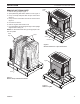

58D6002
13
Unvented Cast Iron Gas Stoves
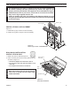
The heater gas inlet connection is 3/8" NPT at the valve.
The inlet is located on left side of stove. Remove front
control plate to better access the inlet.
When tightening up the joint to the valve, hold the valve
securely with a wrench to prevent movement.
Test all gas joints from the gas meter to the heater valve
for leaks using a gas analyzer or soap and water solution
after completing connection.
Check the gas pressure with the appliance burning and
the control set to
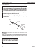
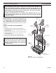
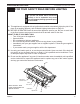
Figure 11
The valve regulator controls the burner pressure which
should be checked at the pressure test point.
If outlet pressure is low, check inlet pressure against data
plates or manual.
Turn captured slotted screw counter clockwise 2 or 3
turns and then place tubing to pressure gauge over test
point (Use test point “OUT” closest to control knob). After
taking pressure reading, be sure and turn captured screw
clockwise firmly to re-seal. Do not over torque. Check for
gas leaks.
Remove control panel to access gas valve.
FP2781
millivolt valve
Test Port "OUT"
FP2781
Figure 11 -
Pressure Test Point Location Millivolt Control
WARNING
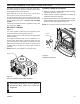
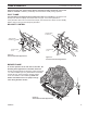
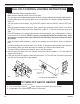
1. Remove cover on control panel to show opening
for remote receiver. Figure 12
2. Follow remote receiver Instructions to make all
necessary wiring connections.
3. Place remote receiver in the opening of control
panel. Use two screws provided to attach remote
receiver to the control panel. Figure 12
Do not place remote in combustion chamber.
O
N
O
F
F
ST1175
remote receiver
Remote
Receiver
Cover
ST1175
Figure 12 -
Install Remote Receiver