UNVENTED GAS CAST IRON STOVE INSTALLATION AND OPERATING INSTRUCTIONS SINGLE DOOR MODELS: CSVF20SNV CSVF30SNV CSVF20SPV CSVF30SPV DOUBLE DOOR MODELS: VFCS20DNV VFCS30DNV VFCS20DPV VFCS30DPV Natural Gas or Propane/LPG Millivolt Control WARNINGS WARNINGS If the information in this manual is not followed exactly, a fire or explosion may result causing property damage, personal injury or loss of life.
CONTENTS Important Safety Information........................... 3 Rock Wool Installation.................................... 18 Product Features............................................... 5 Flame Appearance........................................... 19 Checking Pilot Flame................................... 19 Checking the Burner Flame......................... 20 Dimensions........................................................ 6 Getting Started...................................................
IMPORTANT SAFETY INFORMATION INSTALLER OWNER Please leave these instructions with the appliance. Please retain these instructions for future reference. IMPORTANT warning Read these instructions carefully before installing or trying to operate this vent-free gas heater. • Any change to this heater or its controls can be dangerous. • Improper installation or use of the heater can cause serious injury or death from fire, burns, explosion or carbon monoxide poisoning.
IMPORTANT SAFETY INFORMATION Continued from page 3 14. Caution: Candles, incense, oil lamps, etc. produce combustion by-products including soot. Vent-free appliances will not filter or clean soot produced by these types of products. In addition, the smoke and/or aromatics (scents) may be reburnt in the vent-free appliance which can produce odors. It is recommended to minimize the use of candles, incense, etc. while the vent-free appliance is in operation. 15. This is an unvented gas-fired heater.
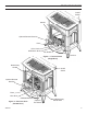
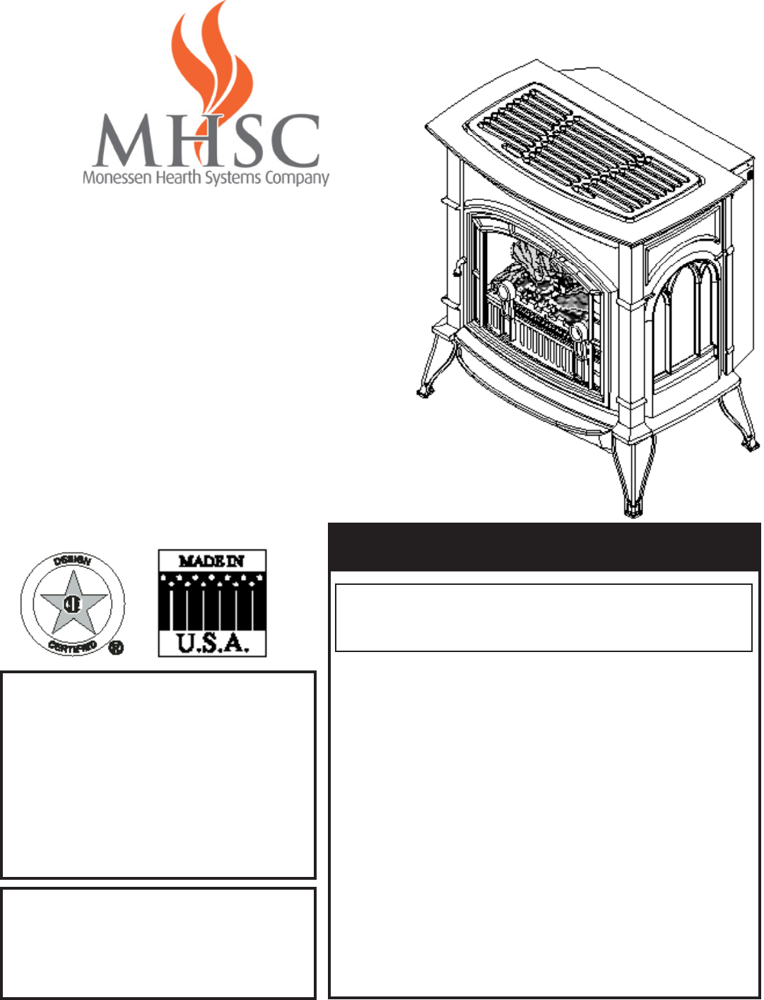
product features On/Off Switch Handle Optional Remote Receiver Piezo Hi/Lo Knob Off/Pilot/On Knob Fan Switch Figure 1 - Cast Iron Stove (Single Door) Break-Away Handle Door On/Off Switch Optional Remote Receiver Piezo Hi/Lo Knob Off/Pilot/On Knob Figure 2 - Cast Iron Stove (Double Door) 58D6002 Optional Fan Switch Store Break-Away Handle Here
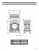
dimensions Figure 3 - Dimensions A B C CSVF20S/VFCS20D 211/4" 23" 161/2" CSVF30S/VFCS30D 263/4" 281/2" 193/4" 58D6002
getting Started Make sure you have received all parts: Check your packing list to verify that all listed parts have been received. You should have the following: • Cast Iron Stove with Burner Assembly • Installation/Operating Instructions • Ceramic Fiber Logs • Touch-up Paint Millivolt controlled heater designed to be operated with optional devices for ON/OFF functions.
PRODUCT SPECIFICATIONS Natural Gas NOTE: An external regulator is required to reduce supply pressure to a maximum of 101/2" w.c. on Natural Gas systems operating at higher pressure. Millivolt Pressure Regulator Pressure Setting: 3.5" w.c. Pilot Regulator: 3.5" w.c. Gas Inlet Pressure: Max. 10 1/2" w. c. Min. 5" w.c. Gas Rate Model Number CSVF20SNV/VFCS20DNV (G-EBL-ES-EMB) CSVF30SNV/VFCS30DNV (G-EBL-ES-EMB) Type Millivolt Millivolt Max. BTU/Hr Min.
warning GENERAL INSTALLATION INFORMATION Do not install the heater … • Where curtains, furniture, clothing, or other flammable objects are less than 42" from the front of the heater. • In high traffic areas. • In windy or drafty areas. CODES Adhere to all local codes or, in their absence, the latest edition of THE NATIONAL FUEL GAS CODE ANSI Z223.1 or NFPA54 which can be obtained from… American National Standards Institute, Inc.
GENERAL INSTALLATION INFORMATION Counter Cast Iron Stove Figure 4 - Example of a Large Room with 1/2 Wall Divider The following formula can be used to determine the maximum heater rating per the definition of unconfined space: BTU/Hr = (L1 + L2) Ft x (W) Ft x (H) Ft 50 x 1000 Consider two connecting rooms with an open area between, with the following dimensions: L1 = 151/2 Ft., L2 = 12 Ft., W = 12 Ft., H = 8 Ft.
warning CLEARANCES / HEIGHT REQUIREMENTS The dimensions shown in Figure 5 are minimum clearances to maintain in installing this heater. Left and right clearances are determined when facing the front of the heater. Follow these instructions carefully to ensure safe installation. Failure to follow instructions exactly can create a fire hazard.
CLEARANCES / HEIGHT REQUIRMENTS Figure 6 - Placing Stove in Alcove Tested Minimum Alcove Dimensions VF20 VF30 Height From Hearth A 38½" 52" Width B 23" 34" Depth C 36" 36" Note: Maintain minimum side and back clearances when placing stove in alcove.
Removing Unit from Crate 1. Remove two (2) straps. See Figure 7. 2. Open plastic bag and slide to bottom of unit. See Figure 8. Plastic Bag Straps 3. Lift up on ash lip and pivot down to open control door. See Figure 9. 4. Lift up on front. Pivot bottom of front out. Remove front. See Figure 9. 5. Lift screen to remove. 6. Remove log box from inside of unit. 7. Lift unit off pallet. Lift unit up high enough to clear upright supports unit is sitting on.
CONNECTING THE GAS caution NOTICE: A qualified gas appliance installer must connect the heater to the gas supply. Consult all local codes. Use new black iron or steel pipe. Internally tinned copper or copper tubing can be used per National Fuel Code, section 2.6.3, providing gas meets hydrogen sulfide limits, and where permitted by local codes. Gas piping system must be sized to provide minimum inlet pressure (Listed on Data Plate) at the maximum flow rate (BTU/Hr).
The heater gas inlet connection is 3/8" NPT at the valve. The inlet is located on left side of stove. Remove front control plate to better access the inlet. When tightening up the joint to the valve, hold the valve securely with a wrench to prevent movement. warning CHECKING GAS PRESSURE and connecting remote receiver Connecting directly to an unregulated propane/L.P.G. tank can cause an explosion.
ELECTRICAL WIRING (Millivolt) caution The millivolt valve is a self-powered combination gas control that does not require 110 Vac to operate. ODS Pilot Label all wires prior to disconnection when servicing controls. Wiring errors can cause improper and dangerous operation. Verify proper operation after servicing.
LOG PLACEMENT warning Before you begin — This unit is supplied with four ceramic fiber logs. Do not handle these logs with your bare hands. Always wear gloves to prevent skin irritation from ceramic fibers. After handling the logs, wash your hands gently with soap and water to remove any traces of fibers. The positioning of the logs are critical to the safe and clean operation of this heater. Sooting and other problems may result if the logs are not properly and firmly positioned in the appliance.
LOG PLACEMENT VF20 Installing logs on grate (See Figure 15) 1. Install back log (#1) on back of burner assembly. 2. Install front log (#2) on 2 pegs on burner assembly. Figure 15 - Installing Logs to Grate (VF20) rock wool installation (VF30 Units only) 1. Break rock wool into dime-sized pieces. ➞ 2. Place rock evenly across rock wool tray and front burner as shown in Figure 16. • Rock wool depth must not be more than 1". • Do not place rock wool past the bend in rock wool tray.
flame appearance Flames from the pilot, front and rear burner should be visually checked as soon as the heater is installed. In addition, periodically check the flames visually during operation. Checking pilot flame The pilot flame must always be present when the heater is in operation. It should just touch the top of the thermocouple tip for natural. See Figure 17 for correct pilot flame. If the pilot flame does not touch the thermocouple, then the burners cannot function reliably.
FLAME APPEARANCE CHECKING BURNER FLAME In normal operation at full rate after 15 minutes, the following flame appearances should be observed: The left and right rear flames should be yellow and extend 1"-2" above middle logs. The yellow flames should not contact the logs. There should be glowing embers on the front surface of the middle log. Note: The flames and embers will be an opaque orange color during the burn off time.
OPERATING INSTRUCTIONS warning for your safety read before lighting If you do not follow these instruction exactly, a fire or explosion may result causing property damage, personal injury or loss of life. A. This appliance is equipped with an ignition device which automatically lights the pilot. If the piezo is not working properly, see Match Lighting Instructions, page 24. B. BEFORE OPERATING smell all around the appliance area for gas.
OPERATING INSTRUCTIONS Millivolt CONTROL LIGHTING INSTRUCTIONS 1. STOP! Read the safety information label. 2. Make sure the manual shutoff valve is fully open. 3. This gas log set is equipped with an ignition device (piezo) which automatically lights the pilot. If piezo ignitor does not light the pilot, refer to instructions for Match Lighting Instructions, page 23. 4. Turn gas control knob clockwise to the OFF position, turn ON/OFF switch to OFF position. 5. Wait (5) minutes to clear out any gas.
OPERATING INSTRUCTIONS and Cleaning and Servicing match lightinG instructions 1. Open stove door. Remove any items necessary for easy access to the pilot (for example: logs, screens, etc.). 2. Follow appropriate lighting instructions found previously. Light a match and hold the flame to the end of the pilot and ignite the pilot. 3. After control knob has been released and pilot stays lit, reinstall any items that were removed for pilot access. Close and latch stove door. 4.
replacement parts Burner assembly warning VF20 24 Failure to position the parts in accordance with these diagrams or failure to use only parts specifically approved with this appliance may result in property damage or personal injury.
REPLACEMENT PARTS list REPLACEMENT PARTS ARE AVAILABLE THROUGH YOUR RETAILER.
replacement parts Burner assembly warning VF30 26 Failure to position the parts in accordance with these diagrams or failure to use only parts specifically approved with this appliance may result in property damage or personal injury.
REPLACEMENT PARTS list REPLACEMENT PARTS ARE AVAILABLE THROUGH YOUR RETAILER.
replacement parts list REPLACEMENT PARTS ARE AVAILABLE THROUGH YOUR RETAILER. Logs Item Qty VF30 1 Back Log 1 58D1901 2 Bottom Left Log 1 58D1902 3 Bottom Right Log 1 58D1903 4 Left Top Log 1 58D1904 5 Right Top Log 1 58D1905 warning 28 Description Failure to position the parts in accordance with these diagrams or failure to use only parts specifically approved with this appliance may result in property damage or personal injury.
warning WARNING TROUBLESHOOTING Turn appliance OFF and allow to cool before servicing. Only a qualified service person should service and repair the heater. Note: All troubleshooting items are listed in order of operation. SYMPTOM POSSIBLE CAUSE When ignitor button is pressed, there is no spark at ODS/pilot. 1. Ignitor electrode positioned 1 Replace ignitor. wrong. 2. Ignitor electrode is broken. ACTION 2. Replace ignitor. 3. Ignitor electrode not con- 3. Reconnect ignitor cable.
warning TROUBLESHOOTING If the gas quality is bad, your pilot may not stay lit, the burners may produce soot and the heater may backfire when lit. If the gas quality or pressure is low, contact your local gas supplier immediately. SYMPTOM POSSIBLE CAUSE ACTION ODS/pilot lights, but flame goes out when control knob is released. 1. Control knob not fully pressed 1. Press in control knob fully. in. 2. Control knob not pressed in 2. After ODS/pilot lights, keep control knob pressed in for 30 seconds.
Massachusetts Residents Only — Please read and follow these special requirements NOTE REGARDING VENTED PRODUCTS This product must be installed by a licensed plumber or gas fitter when installed within the Commonwealth of Massachusetts. Any residence with a direct vent product must have a CO detector installed in the residence. Installation of the fireplace or vented gas log in the State of Massachusetts requires the damper to be permanently removed or welded in the fully open position.
Limited Lifetime Warranty MHSC warrants its products to be free of defects in material and workmanship and backs each product with a Limited Lifetime Warranty. This warranty is to the original purchaser of a MHSC product and is not transferable. Lifetime Warranty Covered under this warranty are the stove body, combustion chamber, door frame, gold plating (manufacturing defects only), glass (thermal breakage only), heat exchange system, and burner.