
Operating instructions


13
"MOJO" Series Unvented Gas Log Sets
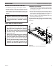
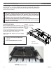
The heater gas inlet connection is a 3/8" NPT at the valve.
On all control type units, the inlet connection is on the right
side of unit. To connect from the opposite side, route the
pipe around the back portion of the unit.
When tightening up the joint to the valve, hold the valve
securely to prevent movement.
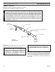
Test all gas joints from the gas meter to the heater valve
for leaks using a gas analyzer or soap and water solution
after completing connection.
Check the gas pressure with the appliance burning and
the control set to .
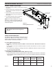
The valve regulator controls the burner pressure which
should be checked at the pressure test point.
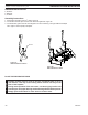
Turn captured screw counter clockwise two or three turns
and then place tubing to pressure gauge over test point
(Use test point “OUT” closest to control knob). After taking
pressure reading, be sure and turn captured screw clock-
wise firmly to re-seal. Do not over torque. Check for gas
leaks.
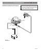
FP2008
gas valve
FP2008
Figure 15 - Pressure Test Point Location
Millivolt Control
Test Port “OUT”