
Operating instructions


15
"MOJO" Series Unvented Gas Log Sets
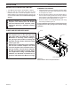
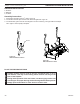
1. Set remote receiver. Refer to instructions included in
receiver kit.
2. Connect the two (2) 1/4" female connec-
tors to the TP/TH and TH terminals on the
control valve.
3. Connect the four-pin connector from the
valve motor to the four-pin connector on
the receiver.
4. For further instruction refer to instruction
sheet included with RCSIT Remote.
FP2010
remote receiver
Figure 17 -
Installing Remote Receiver
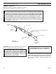
Remote Receiver
Remote Wire
Connectors
Valve
FP2010
Motor
Wires
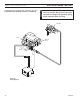
Heat reduces battery life. You can
protect the receiver and extend battery life
by mounting receiver in wall or other location
outside the fireplace.
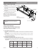
1. If the reading is more than 175 Millivolts and the automatic valve still does not come on, replace
the control.
2. If the closed circuit reading (“A” reading) is less than 175 Millivolts, determine cause for low read-
ing, proceed to Section B below.
1. Check gas pressure to the unit. If gas pressure is within minimum and maximum on data plate,
then check pilot voltage, 500 Millivolts minimum. If the minimum Millivolt reading is not obtainable,
replace pilot.
The Millivolt system and individual components may be
checked with a Millivolt meter having a 0-1000 mV range.
Conduct each check shown in chart below by connection
meter test leads to terminals as indicated.
A Complete 2 & 3 Closed Minimum 175
System
B Thermopile 1 & 2 Open Minimum 500
Output