
Operating instructions


15
Parlor Vent Free Fireplace
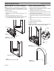
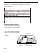
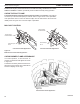
1. Open bottom access door.
. Connect the remote wire connectors to the TH, TH/TP
connections on the valve.
3. Stick Velcro• pads with self-adhesive backing to bottom
of remote receiver and to oor of compartment behind
access panel.
4. Attach remote receiver to rebox with Velcro•
pads. Control switch must face forward.
Do not place remote in combustion
chamber.
FP2561
install remote receiver
Velcro•
Remote
Receiver
Velcro•
FP56
Figure 15 -
Install Remote Receiver
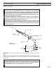
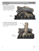
Always check local building codes. This
installation must comply with local regulations as well
as the National Electric Code.
1. Before installing, wire the receptacle into an electrical circuit. This should be done before fram-
ing the replace. Wire with minimum 60° C wire in accordance with prevailing codes.
. Remove the external junction box cover by removing the screw from the left side of the outside
rebox wall. Junction box was installed at the factory.
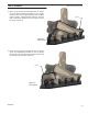
3. The junction box cover has a factory in-
stalled “romex” style strain relief connec-
tor. After connecting the wires, route the
wire leads through this connector. Refer
to the wiring diagram in Figure 16.
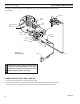
12V Adapter
Light
ON/OFF
Switch
Junction
Box
Ground
120V AC
FP2579
junction box wiring
Figure 16 -
Junction Box Wiring
Diagram