
Operating instructions


15
RFSDV24/34 Freestanding Direct Vent Gas Stove
10003550
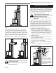
Vertical Through-the-Roof Installation
1. Locate your stove.
2. Plumb to center of the 4” (102 mm) flue collar from
ceiling above and mark position.
3. Cut opening equal to 9C\,” x 9C\,” (240 x 240 mm).
4.
Proceed to plumb for additional openings through
the roof. In all cases, the opening must provide a
minimum of 1” (25 mm) clearance to the vent pipe,
i.e., the hole must be at least 9C\,” x 9C\,” (240 x 240
mm).
5. Place stove into position.
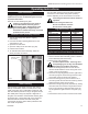
6. Place firestop(s) #7DVFS or Attic Insulation Shield
#7DVAIS into position and secure. (Fig. 24)
If there is a room above ceiling level,
firestop spacer must be installed on both
the bottom and the top side of the ceiling
joists. If an attic is above ceiling level a
7DVAIS (Attic Insulation Shield) must be
installed.
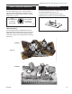
The enlarged ends of the vent section
always face downward. (Fig. 25)
TWL101a
Twist Lock Pipe
2/8/99 djt
#8 Sheet Metal Screws
(3 per joint)
Sealant
Storm Collar
TWL101a
Fig. 25 Roof flashing.
11"
11"
Attic Insulation
Shield
Joist
Ceiling In-
stallation
Joist
Upper Floor
Firestop Spacer
Nails (4)
FP1516
Fig. 24 Place firestop spacer(s) and secure.
11” x 11” (295 x 295 mm)
7. Install roof support (Fig. 22) and roof flashing making
sure upper flange of flashing is below the shingles.
(Fig. 25)
8. Install appropriate pipe sections until the venting is
above the flashing. (Fig. 25)
9. Install storm collar and seal around the pipe.
10. Add additional vent lengths for proper height. (Fig.
23)
11. Apply high temperature sealant to 4” and 7” collars.