8650 Enterprise Drive, Peosta IA 52068-0050 319-556-7484 / Fax 319-556-1235 PARTS LIST FOR HSP-3504-1MGH/1MGV (After Serial #22654) ENGINE OIL GRADE: HONDA: VANGUARD: © Copyright 1999, Mi-T-M Corporation ENGINE OIL CAPACITY: HONDA: VANGUARD: PUMP OIL GRADE: PUMP OIL CAPACITY: FUEL NOZZLE: BTU INPUT: PRESSURE NOZZLE SIZE: SAE 10W-30 ABOVE 40°F=SAE30 BELOW 40°F=SAE10W-30 1 37 OZ. 51 OZ. Mi-T-M PUMP OIL #AW-4085-0016 23.7 OZ. 1.75 60°B DELAVAN 294,000 / HOUR 3.
This Parts Listing has been compiled for your benefit. You can be assured your Mi-T-M hot water pressure washer was constructed and designed with quality and performance in mind. Each component has been rigorously tested to insure the highest level of quality. The contents of this Parts Listing are based on the latest product information available at the time of publication. Mi-T-M reserves the right to make changes in price, color, materials, equipment, specifications or models at any time without notice.
SPECIFICATIONS HSP-3504-1MGH/GV MODEL NUMBER Operating Pressure (PSI/Bar): Water Volume (GPM/lpm): Outlet Water Temperature (F/C): Engine: Horsepower Engine Type Oil Type Oil Capacity (oz./liter) Low Oil Protection Fuel Type Fuel Capacity (gal./liter) Starting HSP-3504-1MGH HSP-3504-1MGV 3500/ 241 (+/- 5%) 3.3/12.
EMF SYSTEM © Copyright 1999, Mi-T-M Corporation OMHSP046-072996-BAR OMHSP045-042699-BAR FLOW CHART 4 EX-9056-052199R1-1C Issue Date: 102097
GENERAL THEORY OF OPERATION WATER FLOW: Connect a pressurized water source to the INLET GARDEN HOSE CONNECTION (1) and turn on the water supply. The water will flow through a WATER STRAINER (2) which has a clear inspection bowl. The water then travels into the TRIPLEX HIGH PRESSURE PUMP (3) which has an UNLOADER (4) that bypasses the water when the trigger gun is closed.
HSP-3504-1MGH/GV-031799-BAR DECAL PLACEMENT © Copyright 1999, Mi-T-M Corporation 6 EX-9056-052199R1-1C Issue Date: 102097
HSP-3504-1MGH/GV-031799-BAR DECAL PLACEMENT REF. # © Copyright 1999, Mi-T-M Corporation DESCRIPTION PART # QTY.
HSP105-031699-BAR FRAME © Copyright 1999, Mi-T-M Corporation 8 EX-9056-052199R1-1C Issue Date: 102097
HSP105A-031699-BAR FRAME © REF. # DESCRIPTION 1 Frame Assembly 2 QTY. REF. # PART # QTY. 5-0120A01 1 17 Engine/Pump Assembly (See exploded drawing) N/A Sep. 1 Wheel 14-0006 4 18 Shim 33-0169 4 3 Jam Nut 30-0117 4 19 Electric Box Assembly (See exploded drawing) N/A Sep.
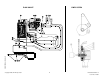
HPS106-031699-BAR ENGINE/PUMP ASSEMBLY © Copyright 1999, Mi-T-M Corporation 10 EX-9056-052199R1-1C Issue Date: 102097
HSP106A-031699-BAR ENGINE/PUMP ASSEMBLY REF # © DESCRIPTION PART # QTY 1MGH QTY 1MGV REF # DESCRIPTION PART # QTY 1MGH QTY 1MGV 1 Hose Gasket 26-0001 1 1 23 Elbow 23-0242 1 1 2 Hose Swivel 23-0095 1 1 24 High Pressure Hose Assembly 15-0194 1 1 3 Strainer Complete (Includes 4-7) 19-0096 1 1 25 Key- Honda 43-0088 1 - 4 Strainer Bowl 19-0103 1 1 - Key- Vanguard 43-0089 - 1 5 Stainless Steel Screen 19-0104 1 1 26 Oil Drain Plug w/Engine N/A 1 1 6 Str
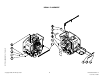
OMPMP024-051297-BAR HIGH PRESSURE PUMP (3-0144) © Copyright 1999, Mi-T-M Corporation 12 EX-9056-052199R1-1C Issue Date: 102097
0MPMP024-051297-BAR HIGH PRESSURE PUMP (3-0144) REF. # © DESCRIPTION PART # QTY. REF. # DESCRIPTION PART # QTY. REF. # DESCRIPTION PART # QTY. 1 Bolt 27-8380 4 20 Bolt 27-8381 4 39 Spacer (See 70-0173) N/A Sep. 3 2 Washer 26-0159 4 21 Gasket 26-0139 1 40 Spring (See 70-0173) N/A Sep. 3 3 Oil Seal 46-0538 1 22 Oil Sight Gauge 22-0123 1 41 Washer (See 70-0173) N/A Sep.
Fig. A Fig. B PUMP SERVICE GUIDE DISASSEMBLY OF THE DISCHARGE VALVE ASSEMBLY 1. Disconnect all plumbing for ease in servicing. 2. Inspect oil for proper level, presence of water or discoloration and replace as needed. 3. With a standard M6 allen wrench remove the eight (8) socket head screws from the manifold. Remove the outer screws first, then the center screws. 4.
REASSEMBLY OF SEAL ASSEMBLY Fig. I 1. Examine Seal Retainers and replace if worn or damaged. Install on Plunger Rod and press into crankcase with tab out. 2. Place Inlet Manifold on work surface with small I.D. ports up. 3. Lubricate new Lo-Pressure Seal and press into position with garter spring down. Be certain the seal is seated squarely on the shoulder on the inlet manifold chamber (Fig. I). 4. Place Inlet Manifold on work surface with larger I.D. ports up. 5.
OMHSP080-120498-BAR UNLOADER/MANIFOLD ASSEMBLY © Copyright 1999, Mi-T-M Corporation 16 EX-9056-052199R1-1C Issue Date: 102097
OMHSP080-120498-BAR UNLOADER/MANIFOLD ASSEMBLY REF. # DESCRIPTION PART # QTY.
UNLOADER (850-0252) OMGEN163-101298-BAR UNLOADER (850-0252) OMGEN163-101298-BAR REF. # DESCRIPTION Copyright 1999, Mi-T-M Corporation 18 QTY.
PRESSURE SETTING & TROUBLESHOOTING THE UNLOADER TOOLS NEEDED: 5000 PSI gauge 2.5mm Allen Wrench Small Flathead Screw Driver Adjustable Wrench TO SET MAXIMUM SPRAY PRESSURE AND BYPASS PRESSURE: Refer to Parts Listing on pg.18. Install the test gauge in the auxiliary port on unloader or in discharge line after the unloader valve. With the pump operating but the trigger gun off, loosen the SET SCREW (3) and remove the COVER (2). Remove both HEX NUTS (1) and set aside. Using the 2.
PRESSURE SWITCH (850-0173) 850-0173-051497-BAR PRESSURE SWITCH (850-0173) 850-0173-051497-BAR REF # DESCRIPTION 1 Pressure Switch Complete (Inc. 2-20) 2 Copyright 1999, Mi-T-M Corporation 20 QTY 850-0173 1 Screw N/A 4 3 Cover N/A 1 4 O-ring N/A 1 5 Micro Switch N/A 1 6 Hex Nut N/A 2 7 Screw N/A 2 8 Housing N/A 1 9 O-ring N/A 1 10 Bushing Nut N/A 1 11 Wire Assembly N/A 1 12 O-ring N/A 1 13 Spring Housing N/A 1 14 O-ring (See 70-0007) N/A Sep.
DETERGENT INJECTOR (50-0052) OMGEN284-052898-DCE DETERGENT INJECTOR (50-0052) REF. # DESCRIPTION 1 Orifice (2.1mm) 2 Injector Body 3 PART # QTY. 50-0057 1 N/A 1 Spring (See 852-0056) N/A Sep. 1 4 Ball (See 852-0056) N/A Sep. 1 5 O-ring (See 852-0056) N/A Sep. 1 6 Piston Retainer 50-0156 1 7 Spring 49-0056 1 8 O-ring (See 852-0056) N/A Sep.
HSP083-120498-BAR HEAT EXCHANGER/EMF SYSTEM © Copyright 1999, Mi-T-M Corporation 22 EX-9056-052199R1-1C Issue Date: 102097
OMHSP083-120498-BAR HEAT EXCHANGER/EMF SYSTEM REF. # © DESCRIPTION PART # QTY. REF. # DESCRIPTION 1 Boiler Assembly Complete 850-0226 1 23 Pin 2 EMF Assembly 850-0257 1 24 3 Hex Nut 30-3022 2 4 Fuel Pump Coupler 33-0225 5 Nut 6 PART # QTY. 33-0211 1 Tensioner Sheave Shaft Assembly (Inc.
BOILER ASSEMBLY (850-0226) 850-0226-112097-BAR HSP111-042799-BAR ELECTRODE GAP SETTINGS © Copyright 1999, Mi-T-M Corporation 24 EX-9056-052199R1-1C Issue Date: 102097
850-0226-112097-BAR BOILER ASSEMBLY (850-0226) REF. # © DESCRIPTION PART # QTY. REF. # DESCRIPTION PART # QTY.
HSP051-051597-JTR GUN (850-0181) & ADJUSTABLE PRESSURE DUAL LANCE (850-0180) © Copyright 1999, Mi-T-M Corporation 26 EX-9056-052199R1-1C Issue Date: 102097
OMHSP051a-051597-JTR GUN (850-0181) & ADJUSTABLE PRESSURE DUAL LANCE (850-0180) REF. # © DESCRIPTION PART # QTY. REF. # DESCRIPTION PART # QTY.
FUEL TANK (850-0248) 850-0193A-012098-BAR FUEL TANK (850-0248) 850-0193-012098-BAR REF. # © Copyright 1999, Mi-T-M Corporation 28 DESCRIPTION PART # QTY. 1 Plug 23-0296 1 2 Fuel Tank (See 850-0193) N/A Sep.
FUEL PUMP (3-0020) & FUEL SOLENOID (44-0100) 0MHSP049/071796/BAR FUEL PUMP (3-0020) & FUEL SOLENOID (44-0100) OMHSP049-071796-BAR REF. # © Copyright 1999, Mi-T-M Corporation 29 DESCRIPTION PART # QTY.
OMHSP072-102698-BAR EMF SYSTEM (850-0257) © Copyright 1999, Mi-T-M Corporation 30 EX-9056-052199R1-1C Issue Date: 102097
OMHSP072A-102698-BAR EMF SYSTEM (850-0257) REF. # © Copyright 1999, Mi-T-M Corporation DESCRIPTION PART # QTY.
OMHSP082-120498-BAR ELECTRIC BOX © Copyright 1999, Mi-T-M Corporation 32 EX-9056-052199R1-1C Issue Date: 102097
OMHSP082-120498-BAR ELECTRIC BOX © Copyright 1999, Mi-T-M Corporation REF. # DESCRIPTION PART # QTY.
OMHSP050A-051697-BAR WIRING SCHEMATIC © Copyright 1999, Mi-T-M Corporation 34 EX-9056-052199R1-1C Issue Date: 102097
OMHSP050B-051697-BAR WIRING DIAGRAM © Copyright 1999, Mi-T-M Corporation 35 EX-9056-052199R1-1C Issue Date: 102097
© Copyright 1999, Mi-T-M Corporation 36 EX-9056-052199R1-1C Issue Date: 102097