IR Digital-1 Digital Wireless Microphone with Mic-On-Chip Technology o w n e r ’ s m a n u a l
TABLE OF CONTENTS Safety . . . . . . . . . . . . . . . FCC Information . . . . . . . . . Welcome . . . . . . . . . . . . . Listening . . . . . . . . . . . . . Specifications . . . . . . . . . . Getting Connected . . . . . . . Descriptions and Functions . Operations . . . . . . . . . . . . Commonly Asked Questions . . . . . . . . . . . . . . . . . . . . . . . . . . . . . . . . . . . . . . .
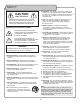
SAFETY 8. Ventilation - The appliance should be situated so its location does not interfere with its proper ventilation. For example, the appliance should not be situated on a bed, sofa, rug, or similar surface that may block the ventilation slots. CAUTION RISK OF SHOCK 9. Heat - The appliance should be situated away from heat sources such as radiators, heat registers, stoves, or other appliances (including amplifiers) that produce heat.
FCC INFORMATION 1. IMPORTANT NOTICE: DO NOT MODIFY THIS UNIT!: This product, when installed as indicated in the instructions contained in this manual, meets FCC requirements. Modifications not expressly approved by Vocopro may void your authority, granted by the FCC, to use this product. 2. IMPORTANT: When connecting this product to accessories and/or another product use only high quality shielded cables. Cable(s) supplied with this product MUST be used. Follow all installation instructions.
WELCOME Welcome And thank you for purchasing the Digital-1 from VocoPro, your ultimate choice in Karaoke entertainment! With years of experience in the music entertainment business, VocoPro is a leading manufacturer of Karaoke equipment, and has been providing patrons of bars, churches, schools, clubs and individual consumers the opportunity to sound like a star with full-scale club models, in-home systems and mobile units.
LISTENING Selecting fine audio equipment such as the unit you’ve just purchased is only the start of your musical enjoyment. Now it’s time to consider how you can maximize the fun and excitement your equipment offers. VocoPro and the Electronic Industries Association’s Consumer Electronics Group want you to get the most out of your equipment by playing it at a safe level.
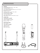
SPECIFICATIONS RECEIVER Carrier Frequency: UHF902 .3 - 927 .7 MHz Bandwidth: 26 MHz Channel Bandwidth: 300 KHz Preset Group: 15 group, 6 frequenceies in each group. Dynamic Range: 96 dB Distortion: < 0.1% Frequency Response: 30-20 KHz/+-2dB Signal/Noise Ratio: 96dB Receiving Sensitivity: -95dBm Transmission Delay: <3 ms Power Supply: DC12V 1A Audio Output: 1x 1/4”, 1 x XLR balance output MICROPHONE Frequency Switch: IR SYNC Output Power: 0 .
GETTING CONNECTED The Digital -1 uses two types of connections: balanced XLR and unbalanced ¼”. One of these connections must be made to the mixer or sound system in order for sound to be heard.
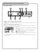
DESCRIPTIONS AND FUNCTIONS FRONT PANEL - RECEIVER 1 2 5 6 3 4 7 1. IR Sensor – This is used to pair and sync the microphone. 2. IR Button – This is used to initialize the pairing mode. 3. Selector Knob – This navigates the menu and is used to confirm a selection. Click knob to confirm selection. 4. Volume – This alters the volume of the microphone audio. 5. Power – This toggles the receiver power on/off. 6.
DESCRIPTIONS AND FUNCTIONS BACK PANEL – RECEIVER 2 3 4 5 1 1 USB CHARGE OUTP UT 5V 500 A m 1. Antenna – These receive the RF/AF transmission from the microphone. 2. Mixed Output – This unbalanced ¼” output sends the microphone audio out to a mixer or sound system. 3. XLR Output – This balanced XLR output sends the microphone audio out to a mixer or sound system. 4. USB Charge Output – This USB will charge the microphone. Output current: 500mA @ 5V. 5.
DESCRIPTIONS AND FUNCTIONS 1 3 IR 2 4 MICROPHONE LO MUTE 1. Display – This shows current frequency, battery level, and transmission level. GROUP CHANNEL 01- 0 6 927.70 Mhz a. Display Icons • – Indicates microphone battery level. The indicator will display remaining battery power. • Mute – This is the microphones mute status. When lit, the microphone audio is muted. Press power button once to toggle the mute feature. • Hi/Lo – This is the microphone transmission status.
OPERATIONS CHANGING THE FREQUENCY: The Digital-1 utilizes a frequency analyzer to provide a graphical view of the environmental interference. The color LCD screen will display a graph of the current interference. Once identified, the frequency can be changed automatically or manually. AUTOMATICALLY: 6 5 RF AF GR/CH SCAN TX PWR HI 4 919.10 MHz 01 06 GR CH 1 1. Press and hold unlock button to access the Menu. 2. Highlight and select the “Scan” option with the Selector Knob. 3.
OPERATIONS MANUALLY: 6 5 RF AF GR/CH SCAN TX PWR HI 4 919.10 MHz 01 06 GR CH 1 1. Press and hold the unlock button the access the Menu. 2. Highlight and select the “GR/CH” option with the Selector Knob. 3. Select from either “GR” or “CH” to modify the channel. a. GR – Refers to the Group of Channels to choose from. There are 15 Groups. b. CH – Refers to the Channels within the Groups. There are 6 channels within each Group. 2 RF AF GR/CH SCAN TX PWR HI 3 919.
OPERATIONS CHANGING THE TRANSMISSION POWER The Digital-1 has two levels of output transmission: high and low. The Low setting has a range of over 100ft. The High setting has a range of over 200ft but consumes the battery at a faster rate. 6 5 RF AF GR/CH SCAN TX PWR HI 4 919.10 MHz 01 06 GR CH 1 1. Press and hold the unlock button to access the Menu. 2. Highlight and select the “TX PWR” option with the Selector Knob. 3. Select from either “High” or “Low” to modify the output power.
COMMONLY ASKED QUESTIONS 1. WHY IS THERE NO MICROPHONE AUDIO? • The mic volume is turned down. • The connections from the Digital-1 recever and the sound system are disconnected. • The microphone needs to be resynced with the receiver. Refer to “changing the frequency”. • The battery is too low. • The microphone is muted. Press power button once to toggle the mute feature. 2. WHY WON’T THE MICROPHONE SYNC? • The IR sensors are not aligned or within range when pairing.
FCC Caution. § 15.19 Labelling requirements. This device complies with part 15 of the FCC Rules. Operation is subject to the following two conditions: (1) This device may not cause harmful interference, and (2) this device must accept any interference received, including interference that may cause undesired operation. § 15.21 Information to user. Any Changes or modifications not expressly approved by the party responsible for compliance could void the user's authority to operate the equipment. § 15.