
Specifications


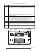


Table 3. RM500/RM500R Rear Panel Items (Cont.)
Item Description Function
7 TX OUT Connector BNC RF output connector, for connection of unfiltered RF transmit signal to
the optional pre/post-selector (PPS)
8 TUNER CONTROL
Connector
Connection of control signals to the optional pre/post-selector (PPS)
9 ACC-J1 to ACC-J4
Connectors
Four 25-pin D-type male connectors, for connection to external accessories,
for example, voice privacy devices, modems, vocoders, etc.
Connector ACC-J2 is used for connection to the parallel I/O interface of the
optional pre/post-selector (PPS)
10 Grounding Screw Connection of ground to the transceiver section
11 TX IN Connector BNC RF input connector, for connection of filtered RF transmit signal from
the optional pre/post-selector (PPS)
12 RX IN Connector BNC RF input connector, for connection of filtered RF receive signal from
the optional pre/post-selector (PPS)
RF OUT
TUNER CONTROL
TX OUT
TX IN
RX OUT
RX IN
REMOTE CONTROL
ACC-J1
ACC-J2
ACC-J3
ACC-J4
110/220VAC
12
987
6
435
1112
10
Figure 4. RM500/RM500R Rear Panel
10 6888882V03