iGuard IP-220E IP/Network Camera User’s Manual Version 2.
CONTENTS Chapter 1 Introduction _________________________________________ 3 1.1 Features ________________________________________________ 3 1.2 Function ________________________________________________ 3 1.3 Package Contents_________________________________________ 4 Chapter 2 iGuard IP-220E Hardware______________________________ 5 Chapter 3 Hardware Installation _________________________________ 6 3.
5.2.3.2 Network_____________________________________________ 41 5.2.3.3 Account Settings ______________________________________ 44 5.2.4 Advanced Settings ______________________________________ 46 5.2.4.1 Event Notification _____________________________________ 46 5.2.4.2 Motion Detection______________________________________ 50 5.2.4.3 Image Recording _____________________________________ 53 5.2.4.4 E-mail / FTP _________________________________________ 54 5.2.4.
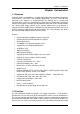
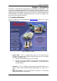
Chapter 1. Introduction Chapter 1 Introduction 1.1 Features iGuard-IP-220E is an affordable, versatile and flexible remote monitoring solution for small business, retail store, and residential applications. It can be accessed from anywhere in the world via a standard browser by entering the IP, account and password. Each system can simultaneously support any one combinations of USB PC cameras be it regular, infrared or pan-tilt.
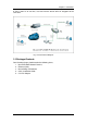
Chapter 1. Introduction in China, and if he or she likes, also check on the branch office in Singapore at the same time. Fig.1 iGuard Network Diagram 1.3 Package Contents Your iGuard package should contain the following items; 1. iGuard IP-220E Network Camera, 2. Ethernet Cable 3. iGuard Utility CD/Software 4. Quick Installation Guide 5. 5.
Chapter 2. :iGuard IP-220E Hardware Chapter 2 iGuard IP-220E Hardware Fig.2 iGuard IP-220E Camera LED Status Indicators on iGuard Light color Green Signal definition Condition description Power state On: Normal power Error Condition On: Error condition occurred Orange Logon state On: When there is user logon and receive the image. Yellow USB data activity Flash when there is transmit/receive on the USB. Red Table.
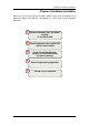
Chapter 3: Hardware Installation Chapter 3 Hardware Installation Before you start using the iGuard IP-220E network camera, you will need to set-up both the hardware and software. The following is a flow chart on the installation procedure: 1 Connect network cable, and power Adapter To iGuard IP-220E 2 Connect Network cable to ROUTER / DSL or Cable modem 3 Setup iGuard Web Manager (Chapter 4) and iGuard-Viewer (Chapter5) (Otional) 4 Router Programming (Appendix).
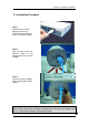
Chapter 3: Hardware Installation 3.1 Installation Procedure Step 1: Connect one end of the Ethernet cable to any available port on your hub, router, or cable/dsl modem. Step 2: Plug the other end of the Ethernet cable to the network port on the iGuard IP-220E. Step 3: Connect DC power adapter output into iGuard IP-220E socket. Warning: Please make sure the input Voltage and Frequency of the DC power adapter (DC 5.
Chapter 4: iGuardware Chapter 4: iGuardware iGuardware is a collection of two utility programs: iGuard Utility and iGuardview. You can use the iGuard Utility to quickly setup multiple iGuard units and you can use iGuardview to monitor multiple cameras, and maybe most importantly to perform motion tracking (V2.5 and above only). If you have a DHCP server on the network, the iGuard will obtain an IP address automatically, and you can enter this IP address in IE to launch the web manager (Chapter 5). 4.
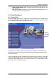
Chapter 4: iGuardware " Adobe Acrobat Reader v5.0 - This will install Acrobat Reader v5.0 on your local hard drive. " Sun Java / ActiveX - Install Sun Java for viewing the video image by Java, or install the OCX for viewing by ActiveX 4.2 Using iGuardware 4.2.1 iGuard Utility The iGuard Utility main menu is shown below. The selection menu is located on the left. The Serial Number, current Firmware and IP Address of every iGuard connected to the LAN will be displayed on the table to the right.
Chapter 4: iGuardware 4.2.1.1 Setup Wizard “Setup Wizard” will take you through the basic configurations step by step. 1. Click to highlight the iGuard on the right that you want to configure. 2. Click on “Setup Wizard”. First, you must enter the device password located on the serial label to enter “Setup Wizard”; or “Launch iGuard”, or “IP Configuration” if the iGuard has a preset password. WARNING: Do not lose this password. If the password is lost, you can not access the device to make changes.
Chapter 4: iGuardware 4. Enter the necessary camera configurations. Choose the appropriate frequency (Indoor 60 Hz, Indoor 50 Hz or Outdoor) to prevent flickering on the video feed. Enter a name for the camera in the “Location” box to easily identify it. 5. Click “Next >” to configure the Network Connection. Fig.
Chapter 4: iGuardware Fig.7 iGuard a/DSL Setup Select “Enable PPPoE connection” and enter your account and password details as provided by your internet service provider (“ISP”). Otherwise, leave it at the default “Disable PPPoE connection” 7. Click “Next >” to change your administrator account and password information. Fig.8 iGuard a/DSL Account Setup An administrator account is necessary to ensure privacy.
Chapter 4: iGuardware password. To reset the iGuard account password, you will need to re-install the firmware using iGuard Utility. 8. Click “Next >” to upload these configuration to iGuard. Fig.9 iGuard PPPoE Setup 9. Click “Next >” to save and restart iGuard with the new configurations. 4.2.1.
Chapter 4: iGuardware Manager(Chapter.5). Click either one to Launch iGuard. Fig.10 Launching iGuard Key in the account name and password entered earlier (if you did not configure one, then revert to the default name “admin” and device password, OR just press ENTER or click on the “Apply” button, if the account name and password was not set and have been deleted). Please refer to Chapter 5 for more details.
Chapter 4: iGuardware Fig.11 iGuard Web Manager 4.2.1.3 IP Configuration This section allows you to set the IP configuration for iGuard. Select the iGuard on the right display screen, and then click “IP Configuration”. This will bring up the IP Address Configuration window. There are two tabs; • • IP Address Advanced (for port setting configuration) When using iGuard for the first time, it is advised to choose the “Using Static IP Address” option.
Chapter 4: iGuardware Fig.12 IP Configuration: Set an IP Address for iGuard Once the IP Address is set, you will be able to connect to iGuard webpage by entering this IP Address into a standard browser. “Obtain an IP address by DHCP or BOOTP” The IP address, Subnet Mask and Gateway is acquired directly and assigned automatically by the system. This “Advanced” section sets security password against unauthorised access to iGuard. Note, this password may be different than the administrator password. Fig.
Chapter 4: iGuardware i. Device Password Use this to set an access password to the individual device. Once set, the user must enter the password to access the device. In addition, the IP Address will not be shown on the right display panel of iGuard Utility. Note: The default device password is set to be the same as administrator password, which is the printed on the serial label. Devise Password enabled. IP Address hidden. Fig.
Chapter 4: iGuardware ii. Management Protocol The administrator can determine the parameter settings when providing access via HTTP (web) to iGuard. For security reasons, the administrator can choose to use either an open or advanced port setting to control these access. The default values are set to port number 80 for HTTP. Once the HTTP port number is set to another port (other than 80), the full IP Address must be entered in order to access the Website.
Chapter 4: iGuardware 3. Select new firmware file (*.bin) and, 4. Click “Start”. The iGuard red and yellow LED will flash alternately to indicate that firmware upgrading is in progress. Once completed, iGuard will reboot.
Chapter 4: iGuardware 4.2.2 iGuardView iGuardView is a PC based utility software that allow you to manage and monitor multiple iGuard cameras located either in a LAN or on a WAN, You can launch the iGuardView program by clicking on “start” - “Program” - “iGuard” “iGuardView” The following Login window will be displayed. By default, the Account Name is set to “Admin” and No Password Fig.
Chapter 4: iGuardware 4.2.2.1 Device Setting : Press the “Enumerate” button, iGuardView will start a search for all iGuard cameras under the same subnet and list them in the main window. Once detected, the following will show in the main window: This shows that the camera is online and active. This shows that the camera is off-line Manually adds the iGuard to be monitored. “Access by iGuard Address” Enter the IP address of the iGuard (example: 192.168.0.30) “Remote Port” This is iGuard UDP port.
Chapter 4: iGuardware : Highlight the iGuard to be deleted from iGuardView’s list. Click “Yes” to confirm deletion of selected iGuard. : Use this function to change iGuard Address & Port Number.
Chapter 4: iGuardware 4.2.2.2 Camera Setting Camera Select: Select either camera A or B Account: Password: If you have setup user account, the information must be entered here. Otherwise access will be denied. Enter the above account password. Image Zoom: Resize the window to between 25% and 200% Camera Rotation: Use this function to keep the camera up-right. Mirror the Image: To mirror the image. Maximum frame per Select from 0.01 fps to a maximum of 30.00 fps.
Chapter 4: iGuardware 4.2.2.3 Motion Detection Setting Enable Motion Detect Click the checkbox to enable Motion Detection. Note: This feature requires the Camera Window be active to work. Click “Monitor” to activate the Window.
Chapter 4: iGuardware Image Compression: Recording AVI File Path Choose from the list of available compressions. Note: This list is dependent on the Codec that is available or already installed on the local PC. To record in MPEC-4, make sure you install or upgrade to Windows Media Player v10. Location where the file will be recorded to. By default, it is recorded to C:\Program Files\iGuard\iGuardView. Click “Browse” to change the file location.
Chapter 4: iGuardware 4.2.2.4 Email Notification Setting You will need to configure the “Message Sender Information” in order for iGuard to send emails. Server Authentication Click “settings…” Enter your Account Name and Account Password if your Server Requires Authentication.
Chapter 4: iGuardware Click “Modify…” to modify the entered Email Address Click “Delete” to remove an email address from the notification list. 4.2.2.5 SNMP Setting Host Name: Provide a Name to identify this device. HTTP Port: Enter the HTTP port assigned for iCAMView. Location: Provide a location for SNMP manager to track device. Manager: Enter a manager’s name for identification.
Chapter 4: iGuardware 4.2.2.6 Camera Monitor : Highlight the iCAMView in the main windows display, and click “Monitor” to view the video stream. Move the curser over the edges of the picture and it will turn into an arrow. Click and hold to pan / tilt the camera (if the camera supports this function) Click this button to record the current image on screen. A window will come up, click “Start” to start recording to the default file and location.
Chapter 4: iGuardware Click this to switch to full screen view. Double click to switch back to current view. Click and drag to resize the window and it’s contents. Date and Time display of live streaming video. Click the left side of the viewing window to bring out more control features. Click on this icon to active two functions; a. Custom window zoom – use this to zoom to your chosen window size. On the video window, LEFT click, hold and drag to the desired window zoom size.
Chapter 4: iGuardware button to go back to the original Click the depressed window size. b. Custom update Window -- use this if you want to monitor only a specific area within the viewing window. On the video window, RIGHT click, hold and drag to the desired window zoom size. A thin line will outline the chosen window size. Release and a smaller window is shown. Video in this smaller window will be updated while those outside are ‘frozen’. Click the depressed button to go back to the original window size.
Chapter 4: iGuardware Click once to tilt the camera up by 1 deg. Click and hold and the camera will tilt increasingly faster upwards. Click once to tilt the camera down by 1 deg. Click and hold and the camera will tilt increasingly faster downwards. Auto Pan (if camera which support this function) Note: The above Pan/Tilt button will only work with cameras supporting the Pan/Tilt function 4.2.2.7 View : Switch between Large or Small icon view Large icon display Small icon display 4.2.2.
Chapter 4: iGuardware : Set the SNMP Parameter. : Display iGuardView version, Copyright information and product service contact. 4.2.2.
Chapter 5: iGuard Web Manager Chapter 5: iGuard Web Manager 5.1 Introduction If you have connected the iGuard to an internal network with a DHCP server, the IP property (IP address, Mask, and Gateway) will be automatically assigned. 1. Start the Web Brower (Netscape or Internet Explore) 2. Enter the iGuard IP Address(e.g. 192.168.0.30) and press ENTER as in Fig.6 Fig.17 Enter iGuard IP address 3. A login screen will appear as in Fig.7.
Chapter 5: iGuard Web Manager The iGuard webpage main menu is divided into two sections. The selection menu on the left and display menu on the right. The selection menu consists of the following options: • • • • Web-Camera Selection Information Basic Settings Advanced Settings Fig.19 iGuard Web Manager Main Menu When using iGuard for the first time, you must set the following to ensure that iGuard works properly; a. b. Set the necessary parameters in the “Configuration” menu.
Chapter 5: iGuard Web Manager 5.2.1 Web-Camera Selection Click on either “ActiveX” or “Sun Java” from Camera A or B to view the camera images. By default the first USB camera connected to iGuard will be denote as “Camera A” Click “Camera B” to view camera B. Note: ActiveX can only function on Windows platform and a plug-in has to be installed on the client's computer. If this is prohibited for safety reasons you will have to use Sun Java to view the video feed.
Chapter 5: iGuard Web Manager To change Video Codec, click Note: The availability of Codec depends on weather the individual user has it installed on the PC or not. Download and install Windows Media Player 10 to enable MPEG4 codec. Digital Zoom In, Digital Zoom Out Rotate Left, Rotate Right Flip the image vertically. Auto Pan the camera Pan Left by 5 deg / Pan Left by 1 deg. Pan Right by 1 deg / Pan Right by 5 deg. Tilt Up by 5 deg / Tilt Up by 1 deg. Tilt Down by 1 deg / Tilt Down by 5 deg.
Chapter 5: iGuard Web Manager Fig.20 iGuard System Status 5.2.2.2 Current Connections This will show all the users currently viewing either Camera A or Camera B. It also lists, the login time, and total bytes received. The user has an option to block the IP or even disable the account of any errant viewer. The administrator privilege will be required for this feature. A total of 10 connections can be displayed at the same time.
Chapter 5: iGuard Web Manager Fig.21 iGuard Current Connections 5.2.2.3 Event Log This will keep a record of all events that occurred in iGuard. The user can Refresh, Clear or Save the log file.
Chapter 5: iGuard Web Manager Fig.22 iGuard Event Log 5.2.3 Basic Settings 5.2.3.1 Camera Settings Use this to set up the USB camera. i.
Chapter 5: iGuard Web Manager Fig.23 Individual Camera Configuration “Image Size” Choose between 640x480, 320x240,etc. The higher the image size, the better the image quality, the slower the frame rate for network transmission. “Anti Flicker” Choose between 50Hz, 60Hz or Outdoors. Note: If you do not choose the right frequency, the image will flicker or lines will appear on the images. “Maximum Number of Connections (1-30)” Use this to limit the number of users that can connect to this camera.
Chapter 5: iGuard Web Manager Choose from the automatic “0 degree (upright)”, to 90, 180 (upside down), and 270 degree position of the camera. This is to facilitate the ability to reposition the camera in any way the user desires. “Pan” Choose between “Normal” for regular placement or “Reverse” when the camera is placed upside down. “Tilt” Choose between “Normal” for regular placement or “Reverse” when the camera is placed upside down. Click “Apply” to save changes. Otherwise, all changes will be lost.
Chapter 5: iGuard Web Manager Fig.24 iGuard IP Address Settings “IP Address” This item determines iGuard IP Address. “Subnet Mask” This item sets iGuard Subnet Mask. The value is normally 255.255.255.0 “Gateway” This item is to set iGuard Gateway. “Obtain an IP address” This allows the user to choose either to set iGuard IP Address manually or via DHCP. iGuard will reboot after the above settings have been changed. ii. DNS Server IP Fig.
Chapter 5: iGuard Web Manager By default the port number is 9001. iv. Ethernet Fig.27 iGuard Ethernet Settings “Connection Type” This item sets the communication speed between iGuard and the Network. iGuard will reboot after “Connection Type” is changed. v. Dynamic DNS If you use a consumer grade broadband service, the chances are you will have a dynamic IP address.
Chapter 5: iGuard Web Manager “When Connection should be made” The user has a choice of; Disabled : Default setting. iGuard does not dial in Connect always : iGuard will automatically dial in. “Login Name” Enter the login name assigned by your ISP. “Login Password” Enter the password assigned by your ISP. 5.2.3.3 Account Settings This allows you to set up to Eight (8) user account with different permissions for iGuard.
Chapter 5: iGuard Web Manager Determine the username of visitors who can log in. The administrator can set up to 32 case sensitive character names. “Password” Set a password for the visitor’s account. case sensitive passwords. The administrator can set up to 32 “Permission” Determine the permission level to one of “Administrator”, “Operator”, “Viewer” or “No Access” Administrator: Operator: Viewer: No Access: This permission allows the user full access including write permission to all the sections.
Chapter 5: iGuard Web Manager “Permit Hours” When the Permission level is set to either “Operator” or “Viewer”, the Administrator can configure and determine the time to which either permission level can access the camera. Click “Configure” to bring up the following window. You can set up to 4 different Permit Hours (in 24hr format). Click “Apply” to save and “Close” to exit. Fig.32 iGuard Permit Hours Configuration 5.2.4 Advanced Settings 5.2.4.
Chapter 5: iGuard Web Manager Fig.33 iGuard Event Notification Page i. Event Notification “Send Email” To activate Event Notification, you will need to set “Send Email” to “Yes”. Select “No” if you do not wish to send out any notification. “Email Server” A valid “Email Server” with username and password (if authentication is required) must be made available for this feature to work. If you do not have this setup, or wish to change the settings, click on “Edit”.
Chapter 5: iGuard Web Manager to select from the list of events you wish these recipients to be notified of. Fig.34 iGuard Event Selection List By default, all the events are selected; you must click “Apply” to activate them. Close the window to return to the Event Notification Page. Click “Apply” to save your settings. iGuard will send you the following email notification depending on which event you have selected.
Chapter 5: iGuard Web Manager Fig.35 iGuard Event : Start Up Fig.36 iGuard Event : User Login Details (Date, Time, Camera & IP) Fig.
Chapter 5: iGuard Web Manager Fig.38 iGuard Event : Camera A or B Motion Detected 5.2.4.2 Motion Detection This page allows the administrator to set motion detection functions for the cameras. i. Camera A (or Camera B) “Enable” To activate motion detect, the administrator has two options; a. “Always On” or b. “On Schedule”, the administrator can set up to 4 different time slots for motion detection. “Detection Sensitivity” This will determines level of change before motion capture is triggered.
Chapter 5: iGuard Web Manager Fig.39 iGuard Motion Detection Page “Send to FTP Server” This option allows the administrator to send and store the motion detected images on a FTP site. This is useful for future reference and recording purpose. Click “Yes” to activate. “ftp:///” This box allows the administrator to determine the file location within the FTP site. If you have not entered a FTP server, the above will be left .
Chapter 5: iGuard Web Manager “Loop from ## to ##” This will determine the number of suffixes preceding the above filename. Once the last number is reached, the first file will be replaced by the most current image. “Digits” This will determine the number of digits assignable for the above number suffix. The administrator can choose to assign between 1 to 6 digits. Click for an example. “Send Email” To send an email notification of Motion Detection with image, choose “Yes”, otherwise choose “No” Fig.
Chapter 5: iGuard Web Manager . click Click To add all the email address at once, click , or . To remove an entry to remove all entries from the recipient list. to confirm and save the above settings. 5.2.4.3 Image Recording Image recording allows the user to receive an image to either their email account or to a FTP server. The images will be sent over a predetermined interval and a certain period. Fig.41 iGuard Image Recording Page i.
Chapter 5: iGuard Web Manager “Send to FTP Server” & “Send Email” This is similar to the function available in Motion Detection Page. Please refer to 4.2.4.2 for details. Fig.42 iGuard Email of Image Recorded 5.2.4.4 E-mail / FTP This sets up the necessary Email and FTP server information. The administrator will have to enter a valid Account Name and Password to the Email server and/or FTP server.
Chapter 5: iGuard Web Manager Fig.43 iGuard Email / FTP Page i. FTP Settings “FTP Server” The administrator will have to enter the FTP server address here. “Account Name” Enter the FTP account name here. “Password” Enter the corresponding password. Click “Apply” to save the above settings. ii. Email Settings “E-mail Server” The administrator will have to enter the Email server address here. “Sender’s Email Address” This will determines iGuard’s Email address.
Chapter 5: iGuard Web Manager If set to “YES”, the administrator will have to provide the account name and password in order to access the Email server. Otherwise, enter “NO”. “Account Name” Enter the account name or login name to the Email server. “Password” Enter the password for the above account name. Click “Apply” to save the above changes. iii. Sending Test Mail Fig.44 iGuard test mail function You must have the “Email Setting” configured to proceed with “Test Mail”.
Chapter 5: iGuard Web Manager iv. Email Address Book Fig.45 iGuard E-mail Address Book Entry Enter an Email address in the box provided and click “Add Email Address”. The new email address will be added to the list. The administrator can store up to 20 email addresses here. To delete an Email address, just press “Delete”. 5.2.4.5 System Settings This page allows the administrator to set iGuard SNMP settings so it can be used by a NMS (Network Management System) like iGuardView. i. System Time Fig.
Chapter 5: iGuard Web Manager To add a new Timer Server the administrator must first make space by deleting some Time Servers. Once this is done, the add dialog box will appear as below. Click “Back” to return to the System Settings Page. Fig.47 List of Time Server “Time Zone (Relative to GMT)” Select the appropriate time zone for your area. Click “Apply” to save. “System Time (yyyy/mm/dd hh:mm:ss)” This is to manually set iGuard System Time. The format is pre-determined to: yyyy/mm/dd hh:mm:ss.
Chapter 5: iGuard Web Manager Fig.50 SNMP setting ”System Name” This is to give iGuard a name identifiable in a SNMP network. “System Contact” This is to give the administrator a name. “System Location” This is to set iGuard location. “Manager IP Address” This set the IP address where the administrator can manage iGuard from. It is valid for up to 8 IP addresses. To manage iGuard from any IP addresses leave it as *.*.*.*. “Community” This is to set a Community name for NMS.
Chapter 5: iGuard Web Manager i. About This gives crucial information about iGuard’s Firmware Version, Hardware Version and Serial Number. These are required information for service calls. ii. Save / Restore Settings “Save current Configuration” Click “Save” to save the current settings and configuration to your PC. The text file will have a default format of YYYY_MMDD_####.cfg. The administrator can change this, if necessary.
Appendix A: Router Configuration Appendix A: Router Configuration If you have signed up a consumer grade broadband service, and you use a router to share your internet access, you will need to address following three major issues: a. DDNS service b. Port forwarding c. Demilitarized Zone If you are not familiar with those network terms, then you will probably need a network technician to help to setup the iGuard.
Appendix A: Router Configuration Follow the steps below to configure your router. If your particular router manufacturer or model is not listed below, please contact your router manufacturer for further assistance in configuring the router.
Appendix A: Router Configuration 3Com (http://www.3com.com) 3C857-US – OfficeConnect Cable/DSL Gateway 3CRWE52196 – OfficeConnect Wireless Cable/DSL Gateway 1. Log into your router using your router IP. 2. On the main page, select Firewalls on the left side of the page. 3. Select the Virtual Servers tab at the top of the page. 4. Click New on the right side of the page to open the Virtual Server Settings dialog box. 5. Type in the camera’s IP address in the Server IP address text box. 6.
Appendix A: Router Configuration Belkin (http://www.belkin.com) F5D6230-3 – Wireless Cable/DSL Gateway Router 1. Log into your router using your router IP. 2. On the main page, select Virtual Server on the left side of the page under the Securit section. 3. Enter the following information on the page: Line #1: Private IP: Type in the camera’s IP address. Private Port: 80 Type: TCP Public Port: 80 Line #2 Private IP: Private Port: Type: Public Port: Type in the camera’s IP address. 9001 UDP 9001 4.
Appendix A: Router Configuration Description: Internet Port: Type: Private IP address: Private Port iGuard – Camera 9001 to 9001 UDP Type in the camera’s IP address. 9001 to 9001 5. Click Apply Changes to save the settings. The iGuard should now be configured o work with your router and be accessible from the internet.
Appendix A: Router Configuration D-Link (http://www.dlink.com) DI-604/DI – 614+/DI-624 1. Log into your router using your router IP. 2. On the main page, click on Advanced at the top of the page. 3. On the left side of the page, click on Virtual Server. Note: Make sure DMZ host is disabled. If DMZ is enabled, it will disable all Virtual Server entries. 4.
Appendix A: Router Configuration Enabled/Disabled: Enabled For ID#2 Service Port: Service IP: Enabled/Disabled: 9001 Type in the camera’s IP address, for example: 192.168.0.5 Enabled 4. Save your settings. iGuard should now be configured to work with your router and be accessible from the internet. DI714 1. Log into your router using your router IP. 2. On the main page, click on Advanced at the top of the page. 3. Click on Virtual Server Settings on the left side of the page. 4.
Appendix A: Router Configuration Dell TrueMobile 2300 Wireless Broadband Router (http://www.dell.com) 1. Log into your router using your router IP. 2. On the main page, click on Advanced Settings at the top of the page. 3. Go to the Port Forwarding and select Custom Port Forwarding Settings. 4. Check the Enable box. 5. Enter the desired name or description in the Service Name field such as iGuard Web. 6. In the Incoming Ports field, specify port 80 in both boxes. 7.
Appendix A: Router Configuration Linksys (http://www.linksys.com) BEFSR41 – EtherFast Cable/DSL Router BEFSX41 – Instant Broadband EtherFast Cable/DSL Firewall Router with 4-Port Switch/VPN EndPoint BEFW11S4 – Wireless Access Point Router with 4-Port Switch – Version 2 1. Log into your router using your router IP. 2. On the router’s main page, click on Advanced at the top of the page. 3. On the next page, click on Forwarding. 4.
Appendix A: Router Configuration Microsoft (http://www.microsoft.com/hardware/broadbandnetworking) MN-100 – Wired Base Station MN-500 – Wireless Base Station 1. Log into your router using your router IP. 2. Open the Bass Station Management Tool, and then click Security. 3. On the Security menu, click Port Forwarding, and then click Set up persistent port forwarding. 4. In the Enable checkbox, check in the checkbox. 5. In the Description box, type a description of the server field such as: iGuard Web. 6.
Appendix A: Router Configuration NETGEAR (http://www.netgear.com) RP614 – Web Safe Router MR814 – Wireless Router 1. Log into your router using your router IP. 2. Click Advanced -> Port Forwarding on the left side of the page. 3. Click Add Customer Service. 4. Enter the following information on the page: Service Name: iGuard – Web Starting Port: 80 Ending Port: 80 Server IP Address: Type in the camera’s IP address, for example: 192.168.0.5 5. Click Apply to save the settings. 6.
Appendix A: Router Configuration Line #2: Starting Port: Ending Port: Server IP Address: 9001 9001 Type in the camera’s IP address, for example: 192.168.0.5 5. Click Apply to save the settings. iGuard should now be configured to work with your router and be accessible from the internet. FVS318 – ProSafe VPN Firewall 1. Log into your router using your router IP. 2. On the main page, click on Add Service on the left side of the screen. 3. Click Add Customer Service. 4.
Appendix A: Router Configuration D. Local Server Address: Enter the IP address of the camera E. WAN Users Address: Any F. Click Apply. 12. Click Add again. A. For Service name select: iGuard Cam B. Action: ALLOW always C. Local Server Address: Enter the IP address of the camera D. WAN Users Address: Any E. Click Apply. 13. Exit the router setup program. iGuard should now be configured to work with your router and be accessible from the internet.
Appendix A: Router Configuration Proxim (http://www.proxim.com) ORiNOCO BG-2000 Broadband Gateway 1. Log into your router using your router IP. 2. On the router’s main page, click on Setup at the top of the page. 3. On the left side of the page, click on Advanced settings -> Port Forwarding. 4. Check in the checkbox for Enable Port Forwarding. 5. Click New on the right side of the page. 6.
Appendix A: Router Configuration Siemens (http://www.speedstream.com) SpeedStream 2602 – 2-Port DSL/Cable Router SpeedStream 2623 – Wireless DSL/Cable Router SpeedStream 2624 – Wireless DSL/Cable Router 1. Log into your router using your router IP. 2. After you are logged in, click on Advanced Setup -> Virtual Servers. 3.
Appendix A: Router Configuration 9. Click on Add to save these settings. 10. Under the first box, next to the Enable checkbox, type in: iGuard Cam. 11. Under PC (Server), select your camera or the camera’s IP address from the list. If the camera is not listed, select the link titled “My PC is not listed.” 12. Leave Protocol as TCP. 13. Under Internal Port No type in: 9001 14. Under External Port No type in: 9001 15. Click on Add to save these settings.
Appendix A: Router Configuration SMC (http://www.smc.com) SMC2404WBR – Barricada Turbo 11/22 Mbps Wireless Cable/DSL Broadband Router SMC7004VBR – Barricada Cable/DSL Broadband Router SMC7004CWBR – Barricada Wireless Cable/DSL Broadband Router 1. Log into your router using your router IP. 2. After you are logged in, click NAT on the left side of the page. 3. Click on Virtual Server on the left side of the page. 4.
Appendix A: Router Configuration Service Port: Private IP: Enable: 9001 Type in the camera’s IP address, for example: 192.168.0.5 Checked in 4. Click Save to save the settings.
Appendix B: IP Address, Subnet and Gateway Appendix B: IP Address, Subnet and Gateway This section discusses Communities, Gateways, IP Addresses and Subnet masking Communities A community is a string of printable ASCII characters that identifies a user group with the same access privileges. For example, a common community name is “public.” For security purposes, the SNMP agent validates requests before responding.
Appendix B: IP Address, Subnet and Gateway Subnetting and Subnet Masks Subnetting divides a network address into sub-network addresses to accommodate more than one physical network on a logical network. For example: A Class B company has 100 LANs (Local Area Networks) with 100 to 200 nodes on each LAN. To classify the nodes by its LANs on one main network, this company segments the network address into 100 sub-network addresses. If the Class B network address is 150.1.x.
Appendix D: Glossary Appendix C: Glossary The Glossary defines the terms used in this User Manual Term Ethernet Gateway IP IP Address MAC MIB NMS OID Router SNMP TCP/IP Definition Local Area Network technology, originally developed by Xerox Corporation, can link up to 1,024 nodes in a bus network. Ethernet provides raw data transfer in a rate of 10 megabits/sec. with actual throughputs in 2 to 3 megabits/sec. using a baseband (single-channel) communication technique.
Appendix D: Glossary Appendix D: Q&A Q1. I have set a permission level without first setting an "Administrator" first and now I can't change anything. You will need to update the firmware. Download the firmware and use iGuard Utility to upload it into iGuard. Once completed, the Username and Passwords will be reset to default. Always remember to save your iGuard configuration for use later. Q2. Can I use other USB Camera to connect to iGuard? Yes, provided that the camera is using VIMICRO chip.
Appendix D: Glossary Click on either "Camera A (320*240)" or "Camera B (320*240)" to view the image. Click "Refresh" to download the next image. Click "Back" to go back to the above page. Q5. What is the effective length of the USB cable? The industrial Standard for effective USB cable length is 5.0m from source to source. If you so decide to extend the length, you can purchase a USB extension Q6.
Appendix D: Glossary (b) From your PC log-on to your iGuard as Administrator. Enter your username and password for your iGuard.com account. Make sure the "Use Public IP to Register" is set to "Yes" Then Click "Apply" located at the bottom of screen. Note: Please allow 5 minutes for the DDNS server to be updated with your Current WAN IP. If iGuard is connected to a Router or IP Share then; (d) Go to your Address Translation / NAT / Firewall section of your ROUTER.
Appendix D: Glossary (e) In iGuard, goto Basic Settings --> Network --> PPPoE, and enter the details. For users with STATIC IP; proceed directly to (d) or (e). Q10. I'm connecting iGuard to a HUB, how do I set it to access the internet? 1. Make sure that PPPoE section in iGuard is setup to connect to your ISP, and; 2. Make sure that Dynamic DNS in iGuard is setup. Q11. I can not access iGuard Web Manager. I have opened up all the ports. 1.
Appendix D: Glossary At 10 FPS, iGuard will need about 40Kbytes - 90Kbytes of bandwidth. NOTE: bps = bits per second (8 bits =1 Byte) Most ADSL throughput speed varies, and is dependent on distance and environmental constraints. In most cases the actual throughput is only about 75%.