RS16 FS – Manual v.6.1A RS16FS | User’s Guide Version 6.
RS16 FS – Manual v.6.1A Preface About this manual This manual is the introduction of RS16FScontroller and it aims to help users know the operations of the disk array system easily. Information contained in this manual has been reviewed for accuracy, but not for product warranty because of the various environments/OS/settings, Information and specification will be changed without further notice. For any update information, please visit www.Proavio-tech.com and your contact windows.
RS16 FS – Manual v.6.1A Table of Contents Chapter 1 1.1 1.2 1.3 1.4 RAID introduction.......................................... 5 Features........................................................................... 5 Terminology ..................................................................... 6 RAID levels ...................................................................... 9 Volume relationship diagram ......................................... 10 Chapter 2 2.1 2.2 2.3 Getting started ...........
RS16 FS – Manual v.6.1A 3.7.4 3.7.5 3.7.6 3.8 Import and export ................................................................................. 53 Event log .............................................................................................. 54 Reboot and shutdown........................................................................... 55 Logout ............................................................................ 55 Chapter 4 4.1 4.2 4.3 4.4 Rebuild...............................
RS16 FS – Manual v.6.1A Chapter 1 RAID introduction 1.1 Features RS16FScontroller is a high-performance RAID controller. • • Backplane solution Fibre Channel (FC x2) – to – SATA II/SAS (xN bays) RAID controller. Features: • • • • • • • • • • • Front-end 2-ported 4Gb FC ports with load-balancing & failover for high availability. RAID 6, 60 ready. Snapshot without relying on host software. (optional) SATA II drive backward-compatible. One logic volume can be shared by as many as 16 hosts.
RS16 FS – Manual v.6.1A usual without any impact to end users. The "on-the-box" implies that it does not require any proprietary agents installed at host side. The snapshot is taken at target side and done by ULTRASTOR controller. It will not consume any host CPU time thus the server is dedicated to the specific or other application. The snapshot copies can be taken manually or by schedule every hour or every day, depends on the modification.
RS16 FS – Manual v.6.1A LUN Logical Unit Number. A logical unit number (LUN) is a unique identifier which enables it to differentiate among separate devices (each one is a logical unit). GUI Graphic User Interface. RAID width, RAID copy, RAID row (RAID cell in one row) RAID width, copy and row are used to describe one RG. E.g.: 1. One 4-disk RAID 0 volume: RAID width= 4; RAID copy=1; RAID row=1. 2. One 3-way mirroring volume: RAID width=1; RAID copy=3; RAID row=1. 3.
RS16 FS – Manual v.6.1A DG DeGraded mode. Not all of the array’s member disks are functioning, but the array is able to respond to application read and write requests to its virtual disks. SCSI Small Computer Systems Interface. SAS Serial Attached SCSI. iSCSI Internet Small Computer Systems Interface. SAS Serial Attached SCSI. FC Fibre Channel. S.M.A.R.T. Self-Monitoring Analysis and Reporting Technology. WWN World Wide Name. HBA Host Bus Adapter.
RS16 FS – Manual v.6.1A 1.3 RAID levels RAID 0 Disk striping. RAID 0 needs at least one hard drive. RAID 1 Disk mirroring over two disks. RAID 1 needs at least two hard drives. N-way mirror Extension to RAID 1 level. It has N copies of the disk. RAID 3 Striping with parity on the dedicated disk. RAID 3 needs at least three hard drives. RAID 5 Striping with interspersed parity over the member disks. RAID 3 needs at least three hard drives.
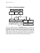
RS16 FS – Manual v.6.1A 1.4 Volume relationship diagram LUN 1 VD 1 LUN 2 LUN 3 VD 2 Snap VD + + + RG PD 1 PD 2 Dedicated CV Global CV PD 3 DS RAM Figure 1.4.1 This is the volume structure of ULTRASTOR designed. It describes the relationship of RAID components. One RG (RAID group) consists of a set of VDs (Virtual disk) and owns one RAID level attribute. Each RG can be divided into several VDs. The VDs in one RG share the same RAID level, but may have different volume capacity.
RS16 FS – Manual v.6.1A Chapter 2 Getting started 2.1 Before starting Before starting, prepare the following items. 1. 2. 3. 4. 5. 6. 7. 8. Check “Certification list” in Appendix A to confirm the hardware setting is fully supported. Read the latest release note before upgrading. Release note accompany with firmware. A server with a FC HBA. FC cables. CAT 5e, or CAT 6 network cables for management port. Prepare storage system configuration plan. Management port network information.
RS16 FS – Manual v.6.1A The target is the storage device itself or an appliance which controls and serves volumes or virtual volumes. The target is the device which performs SCSI commands or bridges to an attached storage device. 2.3 Management methods There are three management methods to manage ULTRASTOR RS16 FS controller, describe in the following: 2.3.1 Web GUI RS16FScontrollers support graphic user interface to manage the system. Be sure to connect LAN cable.
RS16 FS – Manual v.6.1A 2.3.2 Console serial port Use NULL modem cable to connect console port. The console setting is baud rate: 115200, 8 bits, 1 stop bit, and no parity. Terminal type: vt100 Login name: admin Default password: 1234 2.3.3 Remote control – secure shell SSH (secure shell) is required for controllers to remote login. The SSH client software is available at the following web site: SSHWinClient WWW: http://www.ssh.com/ Putty WWW: http://www.chiark.greenend.org.uk/ Host name: 192.168.10.
RS16 FS – Manual v.6.1A “Change IP Config” and “Reset to Default” will rotate by pressing c (up) and d (down). When there is WARNING or ERROR occurred (LCM default filter), the LCM shows the event log to give users more detail from front panel. The following table is function description. System Info. Display system information. Alarm Mute Mute alarm when error occurs. Reset/Shutdown Reset or shutdown controller. Quick Install Quick steps to create a volume.
RS16 FS – Manual v.6.1A [Quick Install] [Volume Wizard] [View IP Setting] RAID 0 RAID 1 RAID 3 RAID 5 RAID 6 RAID 0+1 xxx GB [Local] RAID 0 RAID 1 RAID 3 RAID 5 RAID 6 RAID 0+1 [JBOD x] cd RAID 0 RAID 1 RAID 3 RAID 5 RAID 6 RAID 0+1 [IP Config] [Static IP] [IP Address] [192.168.010.050] [IP Subnet Mask] [255.255.255.0] [IP Gateway] [192.168.010.
RS16 FS – Manual v.6.1A 1. 2. 3. 2.4.3 The system buzzer alarms 1 second when system boots up successfully. The system buzzer alarms continuously when there is error occurred. The alarm will be stopped after error resolved or be muted. The alarm will be muted automatically when the error is resolved. E.g., when RAID 5 is degraded and alarm rings immediately, user changes/adds one physical disk for rebuilding. When the rebuilding is done, the alarm will be muted automatically.
RS16 FS – Manual v.6.1A Chapter 3 Web GUI guideline 3.1 Web GUI hierarchy The below table is the hierarchy of web GUI.
RS16 FS – Manual v.6.1A Reboot and Æ Reboot / Shutdown shutdown Sure to logout? Logout 3.2 Login ULTRASTOR RS16 FS controller supports graphic user interface (GUI) to operate the system. Be sure to connect the LAN cable. The default IP setting is DHCP; open the browser and enter: http://192.168.10.50 (Please check the DHCP address first on LCM.) Click any function at the first time; it will pop up a dialog for authentication.
RS16 FS – Manual v.6.1A 3. Voltage light: Green means normal voltage. Red represents abnormal voltage.. 4. UPS light: Green means UPS works well. Red represents UPS failure. 5. Fan light: Green means Fan works well. Red represents fan failure. (Only for backplane solution) 6. Power light: Green means Power works well. Red represents power failure. (Only for backplane solution) 3.3 Quick install It is easy to use “Quick install” to create a volume.
RS16 FS – Manual v.6.1A Step 2: Confirm page. Click “ a VD will be created. ” if all setups are correct. Then Done. You can start to use the system now. Figure 3.3.2 (Figure 3.3.2: A RAID 0 Virtual disk with the VD name “QUICK16150”, named by system itself, with the total available volume size 271GB.) 3.4 System configuration “System configuration” is designed for setting up the “System setting”, “IP address”, “Login setting”, “Mail setting”, and “Notification setting”. Figure 3.4.
RS16 FS – Manual v.6.1A 3.4.1 System setting “System setting” can set system name and date. Default “System name” composed of model name and serial number of this system. Figure 3.4.1.1 Check “Change date and time” to set up the current date, time, and time zone before using or synchronize time from NTP (Network Time Protocol) server. 3.4.2 IP address “IP address” can change IP address for remote administration usage. There are 2 options, DHCP (Get IP address from DHCP server) or static IP.
RS16 FS – Manual v.6.1A Figure 3.4.2.1 3.4.3 Login setting “Login setting” can set single admin, auto logout time and Admin/User password. The single admin can prevent multiple users access the same controller at the same time. 1. 2. Auto logout: The options are (1) Disable; (2) 5 minutes; (3) 30 minutes; (4) 1 hour. The system will log out automatically when user is inactive for a period of time. Login lock: Disable/Enable.
RS16 FS – Manual v.6.1A Figure 3.4.3.1 Check “Change admin password” or “Change user password” to change admin or user password. The maximum length of password is 12 characters. 3.4.4 Mail setting “Mail setting” can enter at most 3 mail addresses for receiving the event notification. Some mail servers would check “Mail-from address” and need authentication for anti-spam. Please fill the necessary fields and click “Send test mail” to test whether email functions are available.
RS16 FS – Manual v.6.1A Figure 3.4.4.1 3.4.5 Notification setting “Notification setting” can set up SNMP trap for alerting via SNMP, pop-up message via Windows messenger (not MSN), alert via syslog protocol, and event log filter.
RS16 FS – Manual v.6.1A Figure 3.4.5.1 “SNMP” allows up to 3 SNMP trap addresses. Default community setting is “public”. User can choose the event log levels and default setting only enables INFO event log in SNMP. There are many SNMP tools. The following web sites are for your reference: SNMPc: http://www.snmpc.com/ Net-SNMP: http://net-snmp.sourceforge.
RS16 FS – Manual v.6.1A Using “System log server”, user can choose the facility and the event log level. The default port of syslog is 514. The default setting enables event level: INFO, WARNING and ERROR event logs. There are some syslog server tools. The following web sites are for your reference: WinSyslog: http://www.winsyslog.com/ Kiwi Syslog Daemon: http://www.kiwisyslog.com/ Most UNIX systems build in syslog daemon. “Event log filter” setting can enable event level on “Pop up events” and “LCM”. 3.
RS16 FS – Manual v.6.1A 1. 2. Biggest capacity of RAID level for user to choose and, The fewest disk number for RAID level / volume size. E.g., user chooses RAID 5 and the controller has 12*200G + 4*80G HDDs inserted. If we use all 16 HDDs for a RAID 5, and then the maximum size of volume is 1200G (80G*15). By the wizard, we do smarter check and find out the most efficient way of using HDDs.
RS16 FS – Manual v.6.1A Figure 3.5.1.2 Step 3: Decide VD size. User can enter a number less or equal to the default number. Then click “ ”. Figure 3.5.1.3 Step 4: Confirm page. Click “ a VD will be created. ” if all setups are correct. Then Done. You can start to use the system now. Figure 3.5.1.4 (Figure 3.5.1.4: A RAID 0 Virtual disk with the VD name “QUICK13573”, named by system itself, with the total available volume size 1862GB.
RS16 FS – Manual v.6.1A 3.5.2 Physical disk “Physical disk” can view the status of hard drives in the system. The followings are operational tips: 1. 2. Mouse moves to the gray button next to the number of slot, it will show the functions which can be executed. Active function can be selected, but inactive function will show in gray color. For example, set PD slot number 11 to dedicated spare disk. Step 1: Mouse moves to the gray button of PD 11, select “Set Dedicated spare”, it will link to next page.
RS16 FS – Manual v.6.1A Figure 3.5.2.3 (Figure 3.5.2.3: Physical disks of slot 1,2,3 are created for a RG named “RG-R5”. Slot 4 is set as dedicated spare disk of RG named “RG-R6”. The others are free disks.) • PD column description: Slot The position of hard drives. The button next to the number of slot shows the functions which can be executed. Size (GB) Capacity of hard drive. RG Name Related RAID group name. Status The status of hard drive. “Online” Æ the hard drive is online.
RS16 FS – Manual v.6.1A “Failed” Æ the hard drive is failed. “Error Alert” Æ S.M.A.R.T. error alert. “Read Errors” Æ the hard drive has unrecoverable read errors. Usage “RD” Æ RAID Disk. This hard drive has been set to RAID. “FR” Æ FRee disk. This hard drive is free for use. “DS” Æ Dedicated Spare. This hard drive has been set to the dedicated spare of the RG. “GS” Æ Global Spare. This hard drive has been set to a global spare of all RGs. “RS” Æ ReServe.
RS16 FS – Manual v.6.1A Set Dedicated spares Set hard drive to dedicated spare of selected RGs. Set property Change the status of write cache and standby. Write cache options: “Enabled” Æ Enable disk write cache. “Disabled” Æ Disable disk write cache. Standby options: “Disabled” Æ Disable spindown. “30 sec / 1 min / 5 min / 30 min” Æ Enable hard drive auto spindown to save power in the period of time. More information 3.5.3 Show hard drive detail information.
RS16 FS – Manual v.6.1A Step 2: Confirm page. Click “ ” if all setups are correct. Figure 3.5.3.2 (Figure 3.5.3.2: There is a RAID 0 with 4 physical disks, named “RG-R0”, total size is 135GB. Another is a RAID 5 with 3 physical disks, named “RG-R5”.) Done. View “RAID group” page. • RG column description: No. Number of RAID group. The button next to the No. shows the functions which can be executed. Name RAID group name. Total(GB) Total capacity of this RAID group.
RS16 FS – Manual v.6.1A “Rebuild” Æ the RAID group is being rebuilt. “Migrate” Æ the RAID group is being migrated. “Scrub” Æ the RAID group is being scrubbed. Health The health of RAID group. “Good” Æ the RAID group is good. “Failed” Æ the hard drive is failed. “Degraded” Æ the RAID group is not completed. The reason could be lack of one disk or disk failure. • RAID The RAID level of the RAID group. Enclosure RG locates on local or JBOD enclosure.
RS16 FS – Manual v.6.1A More information 3.5.4 Show RAID group detail information. Virtual disk “Virtual disk” can view the status of each Virtual disk. The following is an example to create a VD. Step 1: Click “ ”, enter “Name”, choose “RG name”, “Stripe height (KB)”, “Block size (B)”, “Read/Write” mode, “Priority”, “Bg rate” (Background task priority), change “Capacity (GB)” if necessary. Then click “ ”. Figure 3.5.4.1 ” if all setups are correct. Step 2: Confirm page.
RS16 FS – Manual v.6.1A Figure 3.5.4.2 (Figure 3.5.4.2: Create a VD named “VD-01”, related to “RG-R0”, size is 30GB. The other VD is named “VD-02”, initializing to 12%.) Done. View “Virtual disk” page. • VD column description: No. Number of this Virtual disk. The button next to the VD No. shows the functions which can be executed. Name Virtual disk name. Size(GB) Total capacity of the Virtual disk. Right “WT” Æ Write Through. “WB” Æ Write Back. “RO” Æ Read Only. Priority “HI” Æ HIgh priority.
RS16 FS – Manual v.6.1A Bg rate Background task priority. “4 / 3 / 2 / 1 / 0” Æ Default value is 4. The higher number the background priority of a VD has, the more background I/O will be scheduled to execute. Status The status of Virtual disk. “Online” Æ the Virtual disk is online. “Offline” Æ the Virtual disk is offline. “Initiating” Æ the Virtual disk is being initialized. “Rebuild” Æ the Virtual disk is being rebuilt. “Migrate” Æ the Virtual disk is being migrated.
RS16 FS – Manual v.6.1A • #Snapshot Number of snapshot(s) that Virtual disk is taken. RG name The Virtual disk is related to the RG name VD operations description: Extend Extend a Virtual disk capacity. Scrub Scrub a Virtual disk. It’s a parity regeneration. It supports RAID 3 / 5 / 6 / 30 / 50 / 60 only. Delete Delete a Virtual disk. Set property Change the VD name, right, priority and bg rate. Right options: “WT” Æ Write Through. “WB” Æ Write Back. “RO” Æ Read Only.
RS16 FS – Manual v.6.1A 3.5.5 Take snapshot Take a snapshot on the Virtual disk. Auto snapshot Set auto snapshot on the Virtual disk. List snapshot List all snapshot VD related to the Virtual disk. More information Show Virtual disk detail information. Snapshot “Snapshot” can view the status of snapshot. Please refer to next chapter for more detail about snapshot concept. The following is an example to take a snapshot. Step 1: Create snapshot space.
RS16 FS – Manual v.6.1A Figure 3.5.5.3 Step 4: Export the snapshot VD. Move the mouse to the gray button next to the Snapshot VD number; click “Export”. Enter a capacity for snapshot VD. If size is zero, the exported snapshot VD will be read only. Otherwise, the exported snapshot VD can be read / written, and the size will be the maximum capacity to read / write. Figure 3.5.5.4 Figure 3.5.5.5 (Figure 3.5.5.5: This is the list of “VD-01”. There are two snapshots in “VD-01”.
RS16 FS – Manual v.6.1A No. Number of this snapshot VD. The button next to the snapshot VD No. shows the functions which can be executed. Name Snapshot VD name. Used (MB) The amount of snapshot space that has been used. Exported Snapshot VD is exported or not. Right “RW” Æ Read / Write. The snapshot VD can be read / write. “RO” Æ Read Only. The snapshot VD can be read only. • 3.5.6 #LUN Number of LUN(s) that snapshot VD is attaching. Created time Snapshot VD created time.
RS16 FS – Manual v.6.1A every host can access the volume. Choose LUN number and permission, then click “ ”. Figure 3.5.6.1 Figure 3.5.6.2 (Figure 3.5.6.2: ULTRASTOR RS16 FS, VD-01 is attached to LUN 0 and every host can access. VD-02 is attached to LUN 1 and only FC note name which is named “200000051E4214B8” can access.) • LUN operations description: Attach Attach a logical unit number to a Virtual disk. Detach Detach a logical unit number from a Virtual disk.
RS16 FS – Manual v.6.1A • Example 1 Example 1 is to create two VDs in one RG, each VD uses global cache volume. Global cache volume is created after system boots up automatically. So, no action is needed to set CV. Then set a global spare disk. Eventually, delete all of them. Step 1: Create RG (RAID group). To create the RAID group, please follow the procedures: Figure 3.5.7.1 1. 2. 3. 4. 5. Select “/ Volume configuration / RAID group”. “.
RS16 FS – Manual v.6.1A Figure 3.5.7.3 1. 2. 3. 4. 5. Select “/ Volume configuration / Virtual disk”. ”. Click “ Input a VD name, choose a RG Name and enter a size of VD; decide the stripe high, block size, read/write mode and set priority, finally click “ “. Done. A VD has been created. Do one more time to create another VD. Figure 3.5.7.4 (Figure 3.5.7.4: Create VDs named “VD-R5-1” and “VD-R5-2”. Regarding to “RG-R5”, the size of “VD-R5-1” is 50GB, the size of “VD-R5-2” is 64GB.
RS16 FS – Manual v.6.1A Figure 3.5.7.5 1. 2. 3. Select a VD. Input “Host” name, which is a FC node name for access control, or fillin wildcard “*”, which means every host can access to this volume. ”. Choose LUN and permission, then click “ Done. Figure 3.5.7.6 (Figure 3.5.7.6: VD-R5-1 is attached to LUN 0. VD-R5-2 is attached LUN 1.) Tips The matching rules of access control are from top to bottom in sequence. Step 4: Set global spare disk. To set global spare disks, please follow the procedures. 1.
RS16 FS – Manual v.6.1A Figure 3.5.7.7 (Figure 3.5.8.7: Slot 4 is set as global spare disk.) Step 5: Done. They can be used as disks. Delete VDs, RG, please follow the steps listed below. Step 6: Detach LUN from VD. In “/ Volume configuration / Logical unit”, Figure 3.5.7.8 1. 2. 3. Mouse moves to the gray button next to the LUN; click “Detach”. There will pop up a confirmation page. Choose “OK”. Done. Step 7: Delete VD (Virtual disk). To delete the Virtual disk, please follow the procedures: 1. 2. 3.
RS16 FS – Manual v.6.1A Tips When deleting VD, the attached LUN(s) related to this VD will be detached automatically. Step 8: Delete RG (RAID group). To delete the RAID group, please follow the procedures: 1. 2. 3. 4. 5. Select “/ Volume configuration / RAID group”. Select a RG which is no VD related on this RG, otherwise the VD(s) on this RG must be deleted first. Mouse moves to the gray button next to the RG number click “Delete”. There will pop up a confirmation page, click “OK”. Done.
RS16 FS – Manual v.6.1A 1. 2. 3. 4. 5. 6. Temperature sensors: 1 minute. Voltage sensors: 1 minute. Hard disk sensors: 10 minutes. Fan sensors: 10 seconds . When there are 3 errors consecutively, controller sends ERROR event log. Power sensors: 10 seconds, when there are 3 errors consecutively, controller sends ERROR event log. LED status: 10 seconds. Figure 3.6.1 3.6.1 SES configuration SES represents SCSI Enclosure Services, one of the enclosure management standards.
RS16 FS – Manual v.6.1A Figure 3.6.2.1 If “Auto shutdown” has been checked, the system will shutdown automatically when voltage or temperature is out of the normal range. For better data protection, please check “Auto Shutdown”. For better protection and avoiding single short period of high temperature triggering auto shutdown, controllers use multiple condition judgments for auto shutdown, below are the details of when the Auto shutdown will be triggered. 1. 2. 3. 3.6.
RS16 FS – Manual v.6.1A S.M.A.R.T. (Self-Monitoring Analysis and Reporting Technology) is a diagnostic tool for hard drives to deliver warning of drive failures in advance. S.M.A.R.T. provides users chances to take actions before possible drive failure. S.M.A.R.T. measures many attributes of the hard drive all the time and inspects the properties of hard drives which are close to be out of tolerance.
RS16 FS – Manual v.6.1A Figure 3.6.4.1 Currently, the system only supports and communicates with smart-UPS of APC (American Power Conversion Corp.) UPS. Please review the details from the website: http://www.apc.com/. First, connect the system and APC UPS via RS-232 for communication. Then set up the shutdown values when power is failed. UPS in other companies can work well, but they have no such communication feature. UPS Type Select UPS Type. Choose Smart-UPS for APC, None for other vendors or no UPS.
RS16 FS – Manual v.6.1A Battery Level Current percentage of battery level. (%) 3.
RS16 FS – Manual v.6.1A Figure 3.7.2.1 Figure 3.7.2.2 When upgrading, there is a progress bar running. After finished upgrading, the system must reboot manually to make the new firmware took effect. Tips Please contact with tech@enhance-tech.com for latest firmware. 3.7.3 Reset to factory default “Reset to factory default” allows user to reset controller to factory default setting. Figure 3.7.3.1 Reset to default value, the password is: 1234, and IP address to default DHCP. Default IP address: 192.
RS16 FS – Manual v.6.1A values are available in export and not available in import which can avoid confliction/date-deleting between two controllers. That says if one controller already exists valuable data in the disks and user may forget to overwrite it. Use import could return to original configuration. If the volume setting was also imported, user’s current data will be overwritten. Figure 3.7.4.1 1. 2. Import: Import all system configurations configuration.
RS16 FS – Manual v.6.1A Figure 3.7.5.1 The event log is displayed in reverse order which means the latest event log is on the first page. The event logs are actually saved in the first four hard drives; each hard drive has one copy of event log. For one controller, there are four copies of event logs to make sure users can check event log any time when there is/are failed disk(s). Tips Please plug-in any of the first four hard drives, then event logs can be saved and displayed in next system boot up.
RS16 FS – Manual v.6.1A Chapter 4 Advanced operation 4.1 Rebuild If one physical disk of the RG which is set as protected RAID level (e.g.: RAID 3, RAID 5, or RAID 6) is FAILED or has been unplugged/removed, then the status of RG is changed to degraded mode, the system will search/detect spare disk to rebuild the degraded RG to a complete one. It will detect dedicated spare disk as rebuild disk first, then global spare disk. RS16FScontrollers support Auto-Rebuild.
RS16 FS – Manual v.6.1A Tips “Set dedicated spare” is not available if there is no RG or only RG of RAID 0, JBOD, because user can not set dedicated spare disk to RAID 0 & JBOD. Sometimes, rebuild is called recover; they are the same meaning. The following table is the relationship between RAID levels and rebuild. RAID 0 Disk striping. No protection for data. RG fails if any hard drive fails or unplugs. RAID 1 Disk mirroring over 2 disks. RAID 1 allows one hard drive fails or unplugging.
RS16 FS – Manual v.6.1A arrays. JBOD The abbreviation of “Just a Bunch Of Disks”. No data protection. RG fails if any hard drive failures or unplugs. 4.2 RG migration To migrate the RAID level, please follow below procedures. 1. 2. 3. Select “/ Volume configuration / RAID group”. Mouse moves to the gray button next to the RG number; click “Migrate”. Change the RAID level by clicking the down arrow to “RAID 5”.
RS16 FS – Manual v.6.1A Figure 4.2.2 (Figure 4.2.2: A RAID 0 with 4 physical disks migrates to RAID 5 with 5 physical disks.) Figure 4.2.3 (Figure 4.2.3: A RAID 0 migrates to RAID 5, the complete percentage is 14%.) To do migration, the total size of RG must be larger or equal to the original RG. It does not allow expanding the same RAID level with the same hard disks of original RG. The operation is not allowed when RG is being migrated. System would reject following operations: 1. 2. 3. 4. 5. 6. 7. 8.
RS16 FS – Manual v.6.1A 1. 2. 3. Select “/ Volume configuration / Virtual disk”. Mouse moves to the gray button next to the VD number; click “Extend”. Change the size. The size must be larger than the original, and then click “ “ to start extension. Figure 4.3.1 4. Extension starts. If VD needs initialization, it will display an “Initiating” in “Status” and complete percentage of initialization in “R%”. Figure 4.3.2 (Figure 4.3.2: Extend VD-R5 from 20GB to 40GB.
RS16 FS – Manual v.6.1A ordinary VDs in the system. Rollback restores the data back to the state of any time which was previously captured in case for any unfortunate reason it might be (e.g. virus attack, data corruption, human errors and so on). Snap VD is allocated within the same RG in which the snapshot is taken, we suggest to reserve 20% of RG size or more for snapshot space. Please refer to Figure 4.4.1 for snapshot concept. Figure 4.4.
RS16 FS – Manual v.6.1A 4. 5. 6. VD page and the size will show in snapshot column. It may not be the same as the number entered because some size is reserved for snapshot internal usage. There will be 2 numbers in “Snapshot (MB)” column. These numbers mean “Used snapshot space” and “Total snapshot space”. There are two methods to take snapshot. In “/ Volume configuration / Virtual disk”, mouse moves to the gray button next to the VD number; click “Take snapshot”.
RS16 FS – Manual v.6.1A (Figure 4.4.1.2: This is the list of “VD-01”. There are two snapshots in “VD-01”. Snapshot VD “SnapVD-01” is exported to read only, “SnapVD-02” is exported to read/write.) 10. There are two methods to clean all snapshots. In “/ Volume configuration / Virtual disk”, mouse moves to the gray button next to the VD number; click “Cleanup snapshot”. Or in “/ Volume configuration / Snapshot”, click “ ”. 11. Cleanup will delete all snapshots related to the VD and release snapshot space.
RS16 FS – Manual v.6.1A Figure 4.4.2.1 (Figure 4.4.2.1: It will take snapshots every month, and keep the last 32 snapshot copies.) Tips Daily snapshot will be taken at every 00:00. Weekly snapshot will be taken every Sunday 00:00. Monthly snapshot will be taken every first day of month 00:00. 4.4.3 Rollback The data in snapshot VD can rollback to original VD. Please follow the procedures. 1. 2. 3. Select “/ Volume configuration / Snapshot”.
RS16 FS – Manual v.6.1A 2. 3. 4. When making rollback, the original VD cannot be accessed for a while. At the same time, the system connects to original VD and snaps VD, and then starts rollback. During rollback, data from snap VD to original VD, the original VD can be accessed and the data in VD just like it has finished rollback. At the same time, the other related snap VD(s) cannot be accessed. After rollback, the other snapshot VD(s) after the VD which is doing rollback will be deleted.
RS16 FS – Manual v.6.1A top in “/ Volume configuration / Physical disk”. For example, Local, JBOD 1 (vendor model), JBOD 2 (vendor model), …etc. Local means disks in local controller, and so on. The disks in JBOD can be used as local disks. Figure 4.6.1 (Figure 4.6.1: Display all PDs in JBOD 1.) “/ Enclosure management / S.M.A.R.T.” can displays S.M.A.R.T. information of all PDs, including Local and all SAS JBODs.
RS16 FS – Manual v.6.1A Figure 4.6.2 (Figure 4.6.2: Disk S.M.A.R.T. information of Local and JBOD 1, although S.M.A.R.T. supports SATA disk only.) SAS JBOD expansion has some constraints as described in the followings: 1. 2. Up to 4 SAS JBODs can be cascaded. Created RG can not use PDs which located in different controllers. It means that RG can be composed of PDs which are all in Local or one SAS JBOD.
RS16 FS – Manual v.6.1A 3. Global spare disk only supports all RGs which located in the same controller. 4.7 Support Microsoft MPIO MPIO (Multi-Path Input/Output) use multiple physical paths to create logical "paths" between the server and the storage device. In the case which one or more of these components fails, causing the path to fail, multi-path logic uses an alternate path for I/O. So applications can still access their data.
RS16 FS – Manual v.6.1A Appendix A. Certification list • RAM RS16FS RAM Spec: 240-pin, DDR2-533(PC4300), Reg.(register) or UB (Unbufferred), ECC, up to 2GB, 64-bit data bus width (and also 32-bit memory support), x8 or x16 devices, 36-bit addressable, up to 14-bit row address and 10-bit column address.
RS16 FS – Manual v.6.1A • Hard drive RS16FSsupport SATA I, II disks.
RS16 FS – Manual v.6.1A Seagate Barracuda ES.2, ST31000640SS, 1000GB, 7200RPM, SAS 3.0Gb/s, 16M B. Event notifications • PD events Level INFO WARNING ERROR • Disk inserted Disk removed HDD failure Description Disk is inserted into system. Disk is removed from system. Disk is disabled. HW events Level WARNING ERROR INFO INFO INFO • Type Type ECC error ECC error ECC info ECC info SCSI info Description Single-bit ECC error is detected. Multi-bit ECC error is detected.
RS16 FS – Manual v.6.1A INFO WARNING ERROR ERROR Voltage critical Voltage critical shutdown UPS info UPS error UPS error UPS error WARNING SMART T.E.C. WARNING SMART failure ERROR ERROR • RMS events Level • System voltages failed!!! System voltages failed!!! The system will do the auto shutdown immediately. UPS detection succeeded. UPS detection failed. AC loss for the system is detected. UPS Power Low!!! The system will do the auto shutdown immediately. Disk S.M.A.R.
RS16 FS – Manual v.6.
RS16 FS – Manual v.6.1A INFO INFO INFO INFO WARNING • deleted Snapshot taken Snapshot space configured Snapshot rollback started Snapshot rollback finished Snapshot quota reached Battery backup events Level • deleted to obtain extra snapshot space. A snapshot on VD has been taken. Set the snapshot space of VD to MB. Snapshot rollback of VD has been started. Snapshot rollback of VD has been finished. The quota assigned to snapshot is reached.
RS16 FS – Manual v.6.1A • System maintenance events Level INFO INFO INFO INFO WARNING Type System shutdown System reboot FW upgrade start FW upgrade success FW upgrade failure Description System shutdown. System reboot. Firmware upgrade start. Firmware upgrade success. Firmware upgrade failure. C. Known issues 1. LSI Logic FC HBA LSI7204XP-LC cannot connect with FC switch Brocade BR-220E. Workaround solution: Use other FC HBA to connect with FC switch Brocade BR-220E. 2.
RS16 FS – Manual v.6.1A Tips If the OS is 64bit, user can set the block size to any available value. If the OS is 32bit, user must change the block size to larger values than 512B. There will be a confirmation pop-up message when VD size is over 2TB. Figure D.1: (Figure D.1: choose “OK” for 64bit OS, choose “Cancel” for 32bit OS, this step will change block size to 4K automatically.) 2. Mouse moves to the gray button next to the VD number; click “More information”.
RS16 FS – Manual v.6.1A Figure D.2 2. Initialize the disk. Figure D.3 3. Convert to GPT disk for over 2TB capacity. For more detail information about GPT, please visit http://www.microsoft.com/whdc/device/storage/GPT_FAQ.mspx Figure D.
RS16 FS – Manual v.6.1A 4. Format the disk. Figure D.5 5. Done. Figure D.6 6. The new disk is ready to use, the available size = 2.72TB. Figure D.
RS16 FS – Manual v.6.1A Caution If user setups 512B block size for VD and the host/server OS is 32bit, in the last step of formatting disk, user will find OS can not format the disk sector after 2048GB (2TB). 7. Wrong setting result: OS can not format disk sector after 2048GB (2TB). Figure D.
RS16 FS – Manual v.6.1A System information SW version ULTRASTOR RS16 FS 1.0.