
Specifications


Micrel, Inc.
KSZ8895MQ/RQ/FMQ
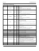
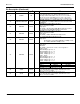
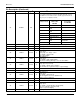
Pin Description (Continued)
Pin Number Pin Name Type
(1)
Port Pin Function
(2)
86 SCONF1 IPD
Pins 91, 86, and 87 are dual MII/RMII configuration pins for the
Port 5 MAC5 MII/RMII and PHY[5] MII/RMII. SW5-MII supports
both MAC mode and PHY modes. P5-MII supports PHY mode
only. See pins configuration below.
Pin# (91, 86, 87)
Port 5 Switch
MAC5 SW5-
MII/RMII
Port5 PHY5
P5- MII/RMII
000 Disable, Otri Disable, Otri
001
PHY Mode MII, or
RMII
Disable, Otri
010
MAC Mode MII, or
RMII
Disable, Otri
011 PHY Mode SNI Disable, Otri
100 Disable (default) Disable (default)
101
PHY Mode MII or
RMII
P5-MII/RMII
110
MAC Mode MII or
RMII
P5-MII/RMII
111 PHY Mode SNI P5-MII/RMII
87 SCONF0 IPD Dual MII/RMII configuration pin. See pin 86 descriptions.
88 GNDD GND Digital ground.
89 VDDC P 1.2V digital core V
DD
.
90 LED5-2 IPU/O 5
LED indicator 2.
Strap option:
Aging setup. See “Aging” section.
PU (default) = aging enable
PD = aging disable.
91 LED5-1 IPU/O 5
LED indicator 1.
Strap option:
PU (default): enable PHY[5] MII I/F.
PD: tristate all PHY[5] MII output. See “Pin 86 SCONF1.”
92 LED5-0 IPU/O 5
LED indicator 0.
Strap option for port 4 only.
PU (default) = Enable auto-negotiation.
PD = Disable auto-negatiation. Strap to register76 bit[7].
93 LED4-2 IPU/O 4 LED indicator 2.
94 LED4-1 IPU/O 4 LED indicator 1.
95 LED4-0 IPU/O 4
LED indicator 0.
Strap option:
PU (default) = Normal mode.
PD = Energy Detection mode (EDPD mode)
Strap to register 14 bits[4:3]
96 LED3-2 IPU/O 3 LED indicator 2.
97 LED3-1 IPU/O 3 LED indicator 1.
98 LED3-0 IPU/O 3
LED indicator 0.
Strap option:
PU (default) = Select I/O drive strength (8mA);
PD = Select I/O drive strength (12mA).
Strap to register132 bit[7-6].
99 GNDD GND Digital ground.
March 12, 2014
20
Revision 1.7