KSZ8864 Evaluation Board User’s Guide KSZ8864 Evaluation Board User’s Guide KSZ8864 Integrated 4-port 10/100 Ethernet Managed Switch Rev 1.1 May 2014 Micrel Inc.
KSZ8864 Evaluation Board User’s Guide Table of contents 1.0 Introduction ........................................................................................................................... 4 2.0 Features ................................................................................................................................. 4 3.0 Evaluation Kit Contents ........................................................................................................ 4 4.0 Hardware Description .......
KSZ8864 Evaluation Board User’s Guide List of Figures and Tables Figure 1 KSZ8864 Evaluation Board ......................................................................................... 5 Figure 2 KSZ8864 Evaluation Board Block Diagram ................................................................ 6 Table 1 Feature Setting Jumpers ................................................................................................. 7 Table 2 Reserved Jumpers ................................................
KSZ8864 Evaluation Board User’s Guide 1.0 Introduction The KSZ8864 is Micrel Operations’ new generation integrated 4-port switch with a 64-pin small package. The KSZ8864 device consists of two PHYs and four MACs. Two of MACs support either MII or RMII interfaces for dual processor/DSP data transfer. Higher speed SPI and MDC/MDIO interfaces can fully manage the 4-port switch by the processor.
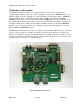
KSZ8864 Evaluation Board User’s Guide 4.0 Hardware Description The KSZ8864 evaluation board is in a compact form factor and can sit on a bench near a computer/laptop. There are three options for configuration: strap in mode; EEPROM mode; and SPI mode. Strap in mode configuration is easily done with on board jumper options. EEPROM mode and SPI mode are accomplished through a built in USB port interface. Using Micrel EEPROM software and your PC, you can reprogram the EEPROM on board by the USB port.
KSZ8864 Evaluation Board User’s Guide KSZ8864 5 VDC Jack EEPROM 3.3V Regulator 1.2V Regulator FIFO, Flow Control, VLAN Tagging, Priority USB Device USB Port Reset Button Mag 1 Mag 2 Port 3 MII Port 4 MII Port 1 Port 2 Port 3 RMII Port 4 RMII Figure 2 KSZ8864 Evaluation Board Block Diagram 4.1 Strap in Mode Strap in configuration mode is the quickest and easiest way to get started. In this mode, the KSZ8864 acts as a standalone unmanaged 4-port switch.
KSZ8864 Evaluation Board User’s Guide read the external EEPROM, if EEPROM does not exist, the chip will use the default values and the strap option setting for all internal registers. 4.1.1 Feature Setting Jumpers The evaluation board provides jumpers to allow the user to easily set strap in configurations for the KSZ8864. Table 1 describes the jumpers and their function in the open or closed state.
KSZ8864 Evaluation Board User’s Guide JP30 JP31 SM3RXD2 SM3RXD1 JP32 SM3RXD0 JP39 JP41 P1LED0 P1LED1 JP42 JP47 3-pin JP49 3-pin P2LED0 Default is 1-2 close for DC from 5V Jack Default is 1-2 close for 3.3V JP50 3-pin Default is 1-2 close for 3.
KSZ8864 Evaluation Board User’s Guide JP4 JP8 JP9 MDIO Serial Bus Config. (PS0) Serial Bus Config. (PS1) Open Open Open 3. 4. Connect the computer’s USB port to the KSZ8864 board with a USB port cable. There are two way to power up the evaluation board: a). Connect the 5 VDC power supply to the KSZ8864 when JP47 pin1-2 is closed. b). 5 VDC power source from the USB port when JP47 pin 2-3 is closed. 5. The KSZ8864 will power up in its default configuration if there is no information in the EEPROM. 6.
KSZ8864 Evaluation Board User’s Guide 7. Open the Windows and navigate to the directory where the Window SPI file is stored. Click its icon to invoke the software. 8. Program the desired settings using the Micrel SPI interface software. See the software operation description section 5.7 for details. 4.4 10/100 Ethernet Ports There are two 10/100 Ethernet ports on the KSZ8864 evaluation board.
KSZ8864 Evaluation Board User’s Guide connects to the port 3 MAC3 in the KSZ8864, and we refer to this as the port 3 Switch SW3-MII/RMII port. Both the SW4-MII and the SW3-MII are default available as PHY modes. SW4-MII can be configured to MAC mode by setting pin [47, 48] =11 and SW3-MII can be configured to MAC mode by setting bit 6 = ‘1’ in the register 223.
KSZ8864 Evaluation Board User’s Guide 4.6.2 Port 3 SW3-MII Jumper and Register Configuration Modes SW3-MII MAC Mode with J9 used SW3-MII PHY Mode with J8 used JP42 Open (default for SW3-MII) Open (default for SW3-MII) Reg 223 Bit6 1 JP24 Pin 2-3 Close JP27 Pin 1-2 Close 0 (default for PHY mode) Pin 2-3 Close Pin 1-2 Close Table 8 Configure for SW3-MII 4.6.
KSZ8864 Evaluation Board User’s Guide 4.6.4 Port 3 SW3-RMII Jumper Configuration for KSZ8864 Modes SW3-RMII MAC to MAC mode with J6 used JP42 Closed SW3-RMII MAC to PHY mode with J7 used Closed JP41 Either Open (clock mode) or Closed (normal mode). Note: When normal mode is used, port 4 SW4-RMII SM4TXC should receive an external 50MHz clock, and then SM3RXC can provides 50MHz clock to SM3TXC and port 3 opposite RMII.
KSZ8864 Evaluation Board User’s Guide folder of MDC_MDIO MIIM of the software directory. For the SMI software to be used all of the registers, please use the software tool in the folder of MDC_MDIO SMI of the software directory. To prepare the KSZ8864 evaluation board for MDC/MDIO configuration follow these steps: 1. Copy the Micrel provided software on your computer. 2. Set JP2, JP3 and JP4 as specified in Table below for the MDC/MDIO configuration.
KSZ8864 Evaluation Board User’s Guide 5.0 Software Description 5.1 Introducing Application Software Tools The Design Kit provides some software tools to support SPI interface, EEPROM (I2C) and MDC/MDIO access for MIIM registers and SMI interface. They are located folders in the software tool directory as follows: 1. In folder of DOS SPI Tool, there is an 8895SPI_DOS.exe file which can be executed directly. The tool is used to access all registers by SPI in a DOS Window. 2.
KSZ8864 Evaluation Board User’s Guide Found New Hardware Wizard window will pop-up and then follow the instructions step by step as below. . Choose ‘No, not this time’ radio button and click the ‘Next’ button. Micrel Inc.
KSZ8864 Evaluation Board User’s Guide Choose the ‘Install from a list or specific location (Advanced)’ radio button and click the ‘Next’ button. Click the ‘Include this location in the search’ check box, and use ‘Browse’ button to select the ‘C:\MicrelEthernetChipConfig\D2XXDriver\CDM 2.02.04 WHQL Certified’ directory and click the ‘Next’ button. The window will install the drivers from this location. Click ‘Finish’ button. The Window will install another driver called ‘USB Serial Converter B’.
KSZ8864 Evaluation Board User’s Guide 5.3 DOS SPI Tool This is a simple and powerful tool to access all register. The tool located in the folder of DOS SPI Tool in the Software tools folder. There is an USBSPI.exe file which can be executed directly by clicking its icon (the software tool support 8864 all registers also). Before run the software tool, the JP9 should be closed, please check the SPI setting in 4.3 SPI mode section.
KSZ8864 Evaluation Board User’s Guide For Read or Write registers, reg is the offset address of the register, value is Hex number. The ‘run file’ command can execute multiple commands by a script file, the script file is a .txt file which can be created by any edit tools. Æ run xxxx.txt //will run the .txt script file. 5.4 MDC/MDIO MIIM Software Tool 5.4.1 MDC/MDIO MII software installation The software tool can be used to access all MIIM registers for PHY based.
KSZ8864 Evaluation Board User’s Guide Select ‘KSZ8864 4 port switch’ and click Next button, Pop up a MDIO MIIM Configuration window as follows: By this window, all of MIIM registers on 2 PHYs can be read and written directly. Click the mark of Down or Up, all MII registers will display for configuration. Check any writable bits of registers and click Write button, the value of registers will be changed. Micrel Inc.
KSZ8864 Evaluation Board User’s Guide 5.5 MDC/MDIO SMI Software Tool 5.5.1 MDC/MDIO SMI software The software tool can be used to access all registers of KSZ8864 by MDC/MDIO interface. This tool locate in folder of MDC_MDIO SMI in the Design Kit, there is MicrelSMIIfApp.exe file which can be executed directly by clicking its icon. 5.5.2 On board jumper setting and Software Application Before run the software tool, the JP2, JP3 and JP4 should be closed, please check the MDC/MDIO setting in section of 4.
KSZ8864 Evaluation Board User’s Guide Read register 1, display value with 0x40 and write bit1=1 to start switch with 0x41. 5.6 EEPROM Software Tool 5.6.1 EEPROM software installation Micrel provides EEPROM software tool can use a PC/Laptop via the on board USB port to program the KSZ8864 evaluation board’s EEPROM without the added expense of an external EEPROM programmer. The software tool can be used to read/write all control registers of the KSZ8864.
KSZ8864 Evaluation Board User’s Guide Select the radio of I2C interface to do EEPROM configuration and press Continue button, pop up a window as follow. Click OK button, one of read/write EEPROM window will display as follow: Micrel Inc.
KSZ8864 Evaluation Board User’s Guide Note: Chip ID1 has to set to 0x00 or 0x01 for EEPROM contents to be downloaded to all registers in current device revision. The software tool can read/write all advanced and port control registers as followed pop-up Windows. Micrel Inc.
KSZ8864 Evaluation Board User’s Guide After change the bits of the registers, the change can be written to EEPROM and save to a file for a back-up. 5.7 Window SPI Software Tool 5.7.1 Window SPI software installation The software tool can be used to read/write all of registers of the KSZ8864. The installation file of the tool is located in folder of Window SPI_I2C_MIIM Tools in the software tools folder of the Design Kit, there is MicrelSwitchPhyTools_1.xx.
KSZ8864 Evaluation Board User’s Guide The control Window includes all registers, static MAC table, LAN table, dynamic table and MIB counter that are supported by SPI. The software can save and open the configuration file. 6.0 Reference Documents KSZ8864 Data Sheet (Contact Micrel for Latest Datasheet), KSZ8864 Design Package includes all design information as a Design Kit (Contact Micrel for the updates). 7.
KSZ8864 Evaluation Board User’s Guide MICREL, INC. 1849 FORTUNE DRIVE SAN JOSE, CA 95131 USA TEL +1 (408) 944-0800 FAX +1 (408) 474-1000 WEB http:/www.micrel.com The information furnished by Micrel in this data sheet is believed to be accurate and reliable. However, no responsibility is assumed by Micrel for its use. Micrel reserves the right to change circuitry and specifications at any time without notification to the customer.