
User`s guide


KSZ8864 Evaluation Board User’s Guide
Micrel Inc. Page 10 5/9/2014
7. Open the Windows and navigate to the directory where the Window SPI file is stored. Click its
icon to invoke the software.
8. Program the desired settings using the Micrel SPI interface software. See the software
operation description section 5.7 for details.
4.4 10/100 Ethernet Ports
There are two 10/100 Ethernet ports on the KSZ8864 evaluation board. The ports J1 and J2 can be
connected to a traffic generator/analyzer or a SmartBit via standard RJ45 connectors using CAT-5
cables. Each port can be used as either an uplink or downlink. All ports support auto MDI/MDIX so
there is no need for cross over cables.
J1 = RJ45 connector for port 1
J2 = RJ45 connector for port 2
4.5 LED indicators
Ethernet Port LEDs
There are two columns of LED indicators, one column for each of the two ports. The LED
indicators are programmable to two different modes. You can program the LED mode through a
strap in option on JP23 or in register 11, bit 1. The mode definitions are shown in Table 5. There are
three LEDs per port. The naming convention is “LEDx_y”, where “x” is the port number, and “y” is
the number of the LED for that port.
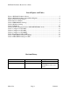
Table 5 LED Modes
Mode 0 Mode1
PxLED1 = Link/Act PxLED1 = 100Link/Act
PxLED0 = Speed PxLED0 = Full Duplex
P1LEDy are assigned to Port1
P2LEDy are assigned to Port2
Power LED
The board also has a power LED D3 for the 3.3V power supply. D3 LED indicates 3.3V Power on
and off.
Interrupt LED
The board also has an Interrupt LED D2 for the Link status change when set the interrupt mask
register 125. D2 LED turns on to indicate the interrupt to be asserted.
4.6 MII/RMII Port Configuration
There are two MII/RMII ports on the KSZ8864. One port connects to the port 4 MAC4 in the
KSZ8864, and we refer to it as the port 4 Switch SW4-MII/RMII port. The second MII/RMII port