
Hydromatic I Chiller Operation Manual
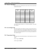
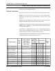
Table Of Contents
- Contents
- Introduction
- System Features
- Operator Controls & Display Panel
- Modes of Operation
- Using the Hydro-matic
- Program Mode
- MAS Settings Not Saved
- Programming Change Notice
- MAS Program Values
- Hydro-Matic Override Toggle Switches
- Trouble Shooting With the Override Toggle Switches
- Program Parameter Table
- Theory of Operation
- Fault Detection and Failsafe Protocols
- Fault Detection and Failsafe Protocols
- Line Voltage Failsafe Protocols
- Sensor Installation Notes
- Applications
- Product Specifications
- Jumper Settings & Part Numbers
- Board Layout and Jumper Locations
- Trouble Shooting Guide
- List of Figures
- List of Tables

PAGE 12
HYDRO-MATIC OPERATIONS MANUAL
REV.03 COPYRIGHT © 1998
P12. Sensors Equipped
Use the chart below to determine the correct code to enter for the sensors
attached to the system:
The allowable range of number is 0-7. The factory default is 1. The marine
Air setting is 2.
P13. Line Voltage Limit
This option programs the minimum operating voltage allowed before a
low power fault is detected. Valid ranges for this parameter are 80 to 100
VAC (for 110 VAC systems) and 180 to 200 VAC (for 220 VAC systems).
The factory default setting is 80 VAC for a 110 Volt system and 180 VAC
for a 220 Volt system.
P14. Temperature Units
This option selects either the Fahrenheit or Celsius temperature scales for
display.
0 selects degrees Fahrenheit.
1 selects degrees Celsius.
Parameter
Val u e
Freon High
Pres Sensor
Freon Low
Pres Sensor
Oil Pressure
Sensor
0
1√√√
2√√
3√
4√
5√√
6√ √
7√