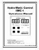
HYDRO-MATIC OPERATIONS MANUAL INTRODUCTION Hydro-matic HMC-1 is a microprocessor-based digital thermostat designed to control chilled water systems. The HMC-1 is capable of controlling multi-stage compressor and heater outputs. This document supports the two models available: the 2-Station Hydro-matic (1 to 2 stage compressor/heater) and the 4-Station Hydro-matic (1 to 4 stage compressor/heater). Each control is available in either reverse cycle or chill cycle for 120 VAC or 240 VAC.
HYDRO-MATIC OPERATIONS MANUAL Automated valve unloading The Hydro-matic unloads the head pressure of the compressor via the optional unloading valves, enabling easier compressor starts. Intelligent compressor sequencing The Hydro-matic sequentially rotates the use of the leading or starting compressor in order to equalize each compressor's cumulative run time.
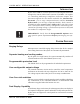
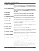
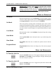
HYDRO-MATIC OPERATIONS MANUAL 1. Outlet Temp Display The seven segment LED display indicates outlet water temperature, program function (in Program Mode) and sensor information (in View Mode). 2. Inlet Temp Display This seven segment LED display indicates inlet water temperature, program parameter value (in Program Mode) and sensor readings (in View Mode). 3. Cool LED When this LED is illuminated, the Hydro-matic is in Cool Mode. 4. Heat LED When this LED is illuminated, the Hydro-matic is in Heat Mode.
HYDRO-MATIC OPERATIONS MANUAL IMPORTANT: Extreme caution must be exercised when switching the override switches while the system is powered on! Improper random staging or improper settings can result in extreme electrical current loading and possible electrical damage. These switches should only be used by experienced personnel with a deliberate plan of intent. MODES OF OPERATION Off Mode When the Hydro-matic is in the Off Mode, all control outputs will be turned off, and the display will be quiescent.
HYDRO-MATIC OPERATIONS MANUAL Selecting Cooling or Heating Pressing the MODE button toggles between Cool and Heat modes. The Cool or Heat LED will be lit, indicating which mode is currently selected. Only one of these modes can be active at a time. Using View Mode Enter View Mode by pressing the VIEW button. View mode will sequentially display each installed item as indicated in Table 1.
HYDRO-MATIC OPERATIONS MANUAL Note: Severe electrical disturbances can sometimes upset the Hydro-matic's operating sequences. Operator confusion related to program parameters can also cause what seem to be operational problems. Whenever there is any doubt as to the proper operation of the Hydro-matic control unit, factory default parameters should be initialized. Important: It is important to insure that the system has been shut down prior to programming the Hydro-matic to avoid any electrical problems.
HYDRO-MATIC OPERATIONS MANUAL Programming Change Notice Program parameters P-1 thru P-14 have default values set by the Hydro-Matic circuit board. Marine Air Systems { MAS } resets program items P-1, P-2, P-5, & P-12. Parameters P-10 & P-11 may also be reset depending on the chiller. MAS Program Values P-1 = 110°F [ 43°C ], P-2 = 48°F [ 9°C ], P-5 = 30 seconds, P-12 = 2, P-10 & P-11 may need to be reset as per the chiller specifications. See Table 2 on page 10 for all other settings.
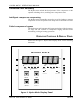
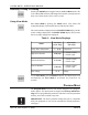
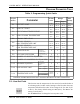
HYDRO-MATIC OPERATIONS MANUAL PROGRAM PARAMETER TABLE Table 2: Programming Quick Guide Prog ram N um be r D efault Va lue P aram eter P -1 HE AT S E T P O INT P -2 C OO L S E T P O INT P -3 HE AT S TA GING TE M P E RATURE P -4 C OO L S TA G ING TE M P E RATURE P -5 S TA G ING TIM E D E L AY P -6 P -7 10 8º F 42 º C 4 9º F 9º C 2º F 2º C 2º F 2º C R ange Low er U pper 9 5º F 35 º C 4 2º F 5 .
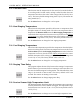
HYDRO-MATIC OPERATIONS MANUAL P-2. Cool Set Point This function sets the temperature for the control to be satisfied when it is in cooling mode. In other words, cooling is called for when the water temperature rises above this value. It has a range of 42º F to 58º F (5.6º to 14º C). The factory default setting setting is 49º F (9º C). The marine Air settig is 48°F (9°C). Use the Select button to change the cool set point. P-3.
HYDRO-MATIC OPERATIONS MANUAL P-7. Service Sensor Low Temperature Limit The service sensor low temperature limit determines whether compressors or heaters are to be used in heating mode on reverse cycle applications and if heaters are equipped. The temperature range for this limit is 25º F to 45º F (-4º to 7º C). The factory default is 35º F (2º C). Use the Select button to change the service sensor low temperature limit. P-8.
HYDRO-MATIC OPERATIONS MANUAL P12. Sensors Equipped Use the chart below to determine the correct code to enter for the sensors attached to the system: Parameter Value Freon High Pres Sensor Freon Low Pres Sensor Oil Pressure Sensor 1 √ √ √ 2 √ √ 0 3 4 √ √ 5 6 √ √ 7 √ √ √ The allowable range of number is 0-7. The factory default is 1. The marine Air setting is 2. P13. Line Voltage Limit This option programs the minimum operating voltage allowed before a low power fault is detected.
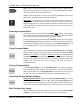
HYDRO-MATIC OPERATIONS MANUAL THEORY OF OPERATION Heating/Cooling Cycles The Cooling and Heating cycles are controlled by four factors: the inlet water temperature, the current operating mode (Heat or Cool), the programmed setpoint (items P-1 and P-2), and the programmed Staging Temperature (items P-3 and P-4). Please note that there are separate setpoints and staging temperatures for heating and cooling. The control algorithm is the same for both heating and cooling.
HYDRO-MATIC OPERATIONS MANUAL matic enables a second compressor. This second compressor will be turned off when the inlet water temperature drops below Level 1. The third and fourth compressors are utilized in the same way, being turned on and off as the inlet water temperature rises above and falls below their particular programmed staging temperatures. Figures 3 through 6 illustrate the system timing of this algorithm under the various heating and cooling modes.
fig 3: System Timing for Reverse Cycle Cooling HYDRO-MATIC OPERATIONS MANUAL REV.
fig 4: System Timing for Reverse Cycle Heating HYDRO-MATIC OPERATIONS MANUAL REV.
fig 5: System Timing for Chill Cycle Cooling HYDRO-MATIC OPERATIONS MANUAL REV.
fig 6: System Timing for Chill Cycle Heating HYDRO-MATIC OPERATIONS MANUAL REV.
HYDRO-MATIC OPERATIONS MANUAL FAULT DETECTION AND FAILSAFE PROTOCOLS Pressure and temperature sensors are monitored for abnormal indications, which may then be flagged as faults. Failsafe Protection There are three levels of reaction to faults detected by the Hydro-matic: Level 0 is the lowest level of protection; non "fatal" faults will be suppressed, and there will be no indications to the user that a fault occurred.
HYDRO-MATIC OPERATIONS MANUAL FAULT DETECTION AND FAILSAFE PROTOCOLS When a fault is detected, it is reported and acted upon according to the programmed failsafe level (P-8). If the service LED is turned on, the Outlet Temp display will also provide a flashing fault code. If the Hydromatic is required to take a compressor off line because of the fault, the LED for that compressor will flash, indicating that an error has been detected.
HYDRO-MATIC OPERATIONS MANUAL If the Hydro-matic is connected to improper voltage during initial powerup, the following messages will be displayed: A-C A Low Power on AC Line Fault (AC) will occur if a system configured for 220V is connected to a 110V supply. "A-C" will flash in the outlet temp display and the Hydro-matic will shut down all outputs. HPF A High Power Fault (HPF) will occur if a system configured for 110V is connected to a 220V supply.
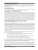
HYDRO-MATIC OPERATIONS MANUAL SENSOR INSTALLATION NOTES Service Sensor Installation The Service sensor should be installed on the condenser coil between the first and second coil opposite the hot gas input, which is usually on the same side as the water outlet. A stainless steel strap should be used to secure it firmly to the condenser. figure 7: Service Sensor Installation Water Sensor Installation Each water sensor should be mounted on the inlet and outlet pipes as shown below.
HYDRO-MATIC OPERATIONS MANUAL APPLICATIONS REV.
HYDRO-MATIC OPERATIONS MANUAL REV.
HYDRO-MATIC OPERATIONS MANUAL REV.
HYDRO-MATIC OPERATIONS MANUAL PRODUCT SPECIFICATIONS GENERAL: Set Point Ranges: Staging Temperature Range (Heating and Cooling) Compressor Service Sensor Range Failsafe Levels Sea Water Pump Cycle Time Heating: 95º F to 118º F Cooling: 42º F to 58º F 1 - 6 Degrees 25º F to 145º F 3 Levels Continuous or Cycle with Compressor ELECTRICAL: Line Voltage AC Aux.
HYDRO-MATIC OPERATIONS MANUAL JUMPER SETTINGS & PART NUMBERS Twenty-Four Volt Control Voltage • JUMPERS EXT-L1 AND EXT-L2 REMOVED 4 Station Cooling Only • JMP 1 IN AND JMP 2 IN • PART NO. ASY-220-A15 115 VOLT • PART NO. ASY-220-A22 220 VOLT • PART NO. ASY-220-C15 115 VOLT 24 VOLT CONTROL • PART NO. ASY-220-C22 220 VOLT 24 VOLT CONTROL 4 Station Reverse Cycle Heating & Cooling • JMP 1 IN AND JMP 2 OUT • PART NO. ASY-220-B15 115 VOLT • PART NO. ASY-220-B22 220 VOLT • PART NO.
BOARD LAYOUT AND JUMPER LOCATIONS
- SYSTEM CONFIGURED FOR 110 VAC IS CONNECTED TO 220 VAC. - REMOVE POWER AS SOON AS POSSIBLE. REPLACE CONTROL FOR ONE CONFIGURED FOR 220VAC. HP(1-4) FLASHES ON THE DISPLAY - HIGH FREON FAULT: OPEN CONTACT IS DETECTED ON PRESSURE SENSOR AFTER COMPRESSOR HAS BEEN RUNNING 15 SECONDS. - IF SENSOR IS EQUIPPED, CHECK PRESSURE SENSOR. - IF SENSOR IS NOT EQUIPPED, PROGRAM ITEM P-12 MUST REFLECT CORRECT CONFIGURATION (see programming options for more detail).
- EIGHT CONDUCTOR DISPLAY CABLE PLUG OR JACK IS DIRTY. - NO LIGHTS ON DISPLAY AND THE SYSTEM DOES NOT HEAT OR COOL. MANUAL OVERRIDE - DISPLAY CABLE IS ASSEMBLED IMPROPERLY. SWITCHES TURN ON OUTPUTS. - CLEAN PLUGS OR JACKS - REPLACE OR ASSEMBLE ANOTHER CABLE. - DISPLAY CABLE IS LOOSE OR UNPLUGGED. - PLUG IN DISPLAY CABLE - OVERRIDE SWITCHES SET TO MANUAL POSITION (LED IS LIT RED). - PLACE OVERRIDE SWITCH TO AUTO POSITION (LED WILL BE LIT GREEN). -TRIAC IS SHORTED INPUT TO OUTPUT.
D ISPLAY B EHAVIOR POWER Off Mode… Display will reset then scroll through "P" - "IP" - "FP" and then blank out. On Mode… Dispaly will reset, appear to be working ok and no buttons will function. VIEW Off Mode… Display will reset, then go blank. On Mode… Dispaly will reset, enter view mode and only the power button will work. SELECT Off Mode… Display will reset, then go blank. On Mode… Display will reset and appear normal, but none of the buttons function.
Contents INTRODUCTION ...................................................................................................... 2 SYSTEM FEATURES ............................................................................................... 2 OPERATOR CONTROLS & DISPLAY PANEL ................................................................. 3 MODES OF OPERATION .......................................................................................... 5 USING THE HYDRO-MATIC ...................................
HYDRO-MATIC OPERATIONS MANUAL List of Figures Figure 1: Hydromatic Display Panel ................................................................................................... 2 Figure 2: Heating and Cooling Cycles .............................................................................................. 11 Figure 3: Typical Cooling Cycle (Reverse Cycle Mode) .................................................................. 13 Figure 4: Typical Heating Cycle (Reverse Cycle Mode) .................