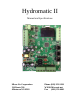
Hydromatic II Manual and Specifications Micro Air Corporation 124 Route 526. Allentown NJ 08501 Phone (609) 259-2636 WWW.Microair.
Introduction The Hydromatic II system is a water temperature controller for use in loop circulation systems. It provides outputs for reverse cycle and electric heater operation at each control. Features Modular system for controlling one to eight compressors. Directly drives AC contactors from 24 to 250 VAC. Integrated touch screen OLED display. Universal 115/230 VAC 50/60 Hz power supply Simple CANBUS (Computer area network) two wire connection between controls.
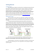
Getting Started CAN Bus Basics The CAN system (Computer Area Network) is a communications protocol system that facilitates communication between electronic controls. Controls are connected to each other to form a network. Typical controls in a network could include ice makers, chilled and heated water systems, air handlers, and direct expansion systems. The physical connection is called a bus and consists of a minimum of two wires connected to each device.
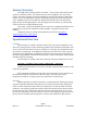
Connecting the control Make connections to the Hydromatic board as shown in the wiring diagram contained in this manual. A freeze sensor, high refrigerant pressure switch, flow switch and low refrigerant pressure switch must be connected to each slave. If a low refrigerant pressure switch is not used in your application, a wire jumper must be installed between the low refrigerant pressure signal connection and low refrigerant pressure ground.
System Overview The Hydromatic system operates as a master – slave system. Each control in the system is considered a slave. The master function can be assigned to any slave in the system. The master function operates independently from the slave function within that control. A slave is designated as a master by making the group ID and unit ID the same value. Additional slaves can be added by setting their unit ID as the next numerically higher unit ID and assigning them to the same group ID as the master.
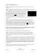
Initial Configuration Step 1: All Hydromatic controls and the pump control must be correctly wired and powered up. Step 2: All Hydromatic controls must be in the off mode. If the display shows a screen saver text scrolling across the display, press any button exit the screen saver. The screen on the right shows a master control in the off mode. If only the menu symbol is shown, the control has been configured as a slave and is in the off mode.
System Menu Items Available menu options depend on the system operating mode. While the system is in heat or cool mode, the user can see a diagnostic view of the system, show the event history, or return to the operating screen. When the system is in the off mode, the user can also change parameters from any slave in the system. Parameter changes made to one slave in the system will change all the slaves in the system. See Appendix 1: System menu overview for a quick overview of the system menu structure.
Operating parameters Purge air Staging delay Cool Mode Set point Heat Mode Set point Hysteresis Differential Variable Speed Enable EL. Heat Transition Sea pump operation Low voltage shutdown VFD Fault Monitor Use Flow For Freeze Pump Flow SW Enable Range 0 to 3 15 to 200 38 to 57 3.3 to 13.9 100 to 140 37.8 to 60 1 to 3 .6 to 1.7 1 to 3 .6 to 1.7 5 to 90 and no 30 to 60, OFF, EHO -1.1 to 15.
Differential The temperature change required to start the next stage. This parameter may be set for 1, 2, or 3 degrees Fahrenheit (.6, 1.1, or 1.7 °C) Variable speed enable (Future option) EL. heat transition (Electric Heat Transition) If the sea water temperature drops below the programmed value, the electric heater or heaters if available will be used and all compressors turned off. This parameter may be set for 40°F to 60°F (4.4°C to 15.6°C).
System setup Brightness Screen saver brightness Service high limit Current limit (Future Option) Freon sensor type * Hi. Pressure maximum PSI * Hi. Pressure 0 PSI Voltage * Low Pressure maximum PSI * Low Pressure 0 PSI Voltage Water Sensor Type # LPS Pressure maximum PSI # LPS Pressure 0 PSI Voltage # HPS Pressure maximum PSI # HPS Pressure 0 PSI Voltage System units Pump Station Delay Reset parameters Range 4 to 15 0 to 8 141 to 159 and Off 60.5 to 70.6 1 to 50 Switch, both 0 to 1016 0 to 2.
Freon sensor type Sets the type of sensor connected to the high and low Freon pressure input. If only a switch is installed, the parameter is set for switch and JP12 and JP 13 must have jumpers installed. If the parameter is set for gauge or both, JP12 and JP 13 jumpers must be removed. The following options will also become available: Hi. Pressure maximum PSI Hi.
Staging parameters Group ID Unit ID Number of slaves Heater on slave (group ID) Heater on slave (group ID + 1) * Heater on slave (group ID + 2) * Heater on slave (group ID + 3) * Heater on slave (group ID + 4) * Heater on slave (group ID + 5) * Heater on slave (group ID + 6) * Heater on slave (group ID + 7) * Enable slave (group ID) Enable slave (group ID + 1) * Enable slave (group ID + 2) * Enable slave (group ID + 3 )* Enable slave (group ID + 4) * Enable slave (group ID + 5) * Enable slave (group ID + 6)
Heater on slave N N is replaced by the unit ID of the control being changed. If the number of slaves is set for 4 and the group ID is 131, you will see menu items for heater on slaves 131 to 134. This parameter allows the user to program which stage an electric heater is installed on. Select “YES” for that slave if an electric heater is connected to the slave or “NO”, if the slave does not have an electric heater connected. Enable slave N N is replaced by the unit ID of the control being changed.
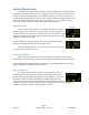
Operation Screen Saver If no buttons are pressed for more than 3 minutes and no faults exist, screen saver text will scroll across the display. Press any button to exit the screen saver. Operating Modes Off mode screen Three modes of operation are available in the Hydromatic II off, cool, and heat. On the master in the off mode, the display shows only the power symbol and the menu symbol. Slaves will show only the menu symbol when the system is off.
Slave Overview Slave Overview The slave overview will be shown when you are viewing is not configured as a master. This view is also available on the master in the diagnostic view. If the return sensor is installed, the tempered water return temperature for the slave is displayed on the top left. The tempered water outlet temperature for the slave is displayed on the top right.
Fault Handling When a slave detects a fault, the slave will turn off the compressor or heater if they are operating. If the fault has been corrected, the master will attempt to restart the slave after two minutes if required. Multiple recurring faults will cause the slave to be locked out by the master. Fault Indication The fault will be indicated at the master by an symbol appearing in place of the slave number.
Slave Bypassed This message is seen at the master as a B on the display in place of the slave number. This indication is not actually a fault but indicates an action was taken by the user to prevent the operation of a slave. VFD Trouble The Variable Frequency Drive (VFD) has reported a fault. See the documentation for the VFD to determine the cause and resolution. Lockout The master keeps fault count for each slave.
Wiring Diagrams Board and Firmware revisions This manual makes reference to Hydromatic II control board printed circuit board (PCB) revisions. The PCB revision is found along the edge of the printed circuit board in white silk screened lettering and starts with PCB-250. PCB-250-00E indicates a revision E circuit board. Firmware revision is shown on the display immediately after applying power. Wiring Diagram Identification The included wiring diagrams are organized by board revision.
Hydromatic II Rev F and Earlier PCB Rev 1.
Hydromatic II Rev G PCB Rev 1.
Pump Relay Wiring Diagram Rev B Rev 1.
Pump Relay Wiring Diagram Rev C Rev 1.
Touch Screen Display Wiring Rev 1.
Specifications Set point range: Cooling 35°F to 57°F 1.7°C to 13.9°C 100°F to 140°F 37.8°C to 60°C Heating Temperature range displayed 5°F to 150°F Sensor accuracy +/-2°F at 77°F Low voltage limit 115 VAC units 75VAC Low voltage limit 230 VAC units 175VAC Line high voltage limit 250VAC Frequency 50 or 60 Hz Heater output MAX Valve output MAX Pump output MAX Compressor output MAX .5 Amps AC .5 Amps AC .5 Amps AC .
CAN bus wire: Compatibility: SAE J1939 Characteristic impedance: 120 ohms Line capacitance: < 80pF per meter at 1 MHz Wire gauge: 20 AWG minimum Specific line delay (velocity factor) : > 70% Mechanical: 2 conductors, twisted pair with shield and drain connection. Examples of acceptable wire: North Wire Data Cell J1939 Waytec CB20-11F 20 Prestolite Wire SAE1939-15 #149812 Rev 1.
Hydromatic II Dimensions (Not to scale) Rev 1.
Pump Control Dimensions (Not to scale) Rev 1.
Glossary (Simplified for Hydromatic II) Bus: A wired connection consisting of 2 or 3 wires connected to each control in a sequentially wired, daisy chain style connection. CAN: Computer Area Network is a communications system that facilitates communication between electronic controls. Differential: The temperature change required to start a stage. This can be set in the Operating Parameters menu. Group ID: A user defined ID number used to permit communications between similar controls.
Appendix 1: System menu overview Diagnostic view View 1 (See manual) View 2 (See manual) Slave View (Master only) Show event history Events 1-8 Copy unit in system (Items in red available only when system is off) Copy slave Operating parameters Purge air Staging delay Heat mode set point Cool mode set point Hysteresis Differential Electric only temperature Sea pump operation Low voltage shut down Back to menu System set up Brightness Screen saver brightness Service high limit Current limit Freon sensor type
Appendix 2: Organizing IDs in the CAN system Controls are addressed on the CAN bus by assigning group ID and unit ID numbers to each control in the system.
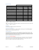
Appendix 3: Ordering a system The Hydromatic II control system is a versatile platform that can be configured as desired for specific system requirements. The number of sensors required depends on the options in your system. Use the table below to determine the number of sensors required for your system.
COPYRIGHT © COPYRIGHT © 2010 to 2015 Micro Air Corporation, All Rights Reserved No part of this publication may be reproduced, translated, stored in a retrieval system, or transmitted in any form or by any means electronic, mechanical, photocopying, recording or otherwise without prior written consent by Micro Air Corporation. Every precaution has been taken in the preparation of this manual to insure its accuracy. However, Micro Air Corporation assumes no responsibility for errors and omissions.