
Hydromatic II Chiller Operation Manual
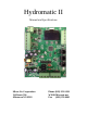
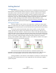
Table Of Contents
- Introduction
- Getting Started
- System Overview
- Operational Overview
- Initial Configuration
- System Menu Items
- Operation
- Fault Handling
- Wiring Diagrams
- Specifications
- Glossary
- Appendix 1: System menu overview
- Appendix 2: Organizing IDs in the CAN system
- Appendix 3: Ordering a system
Page 2
Rev 1.07 ©2015 Micro Air Corp 10/26/2015
Introduction
The Hydromatic II system is a water temperature controller for use in loop
circulation systems. It provides outputs for reverse cycle and electric heater operation at
each control.
Features
Modular system for controlling one to eight compressors.
Directly drives AC contactors from 24 to 250 VAC.
Integrated touch screen OLED display.
Universal 115/230 VAC 50/60 Hz power supply
Simple CANBUS (Computer area network) two wire connection between
controls.
Remote mounted tempered water and sea pump control board with pressure sense
and flow inputs.
Optional stage current sensing and over current shutdown.
Optional high and low Freon pressure transducer inputs.
VFD (Variable frequency drive) dry contact output.
MODBUS input for VFD monitoring.
Electric heat only transitioning based on sea water temperature.
Auxiliary voltage input allows using contactors with operating voltages different
from the supply voltage.
Automatically equalizes compressor run times in multistage systems.
Programmable temperature controlled staging for efficient operation.
Automatic slave bypass and retry for a slave with a fault.
Cycled or continuous sea pump operation.
Compatible with AirNet 5 (internet / network access).
Sea water temperature sensor.
Individual tempered water flow switch inputs for each compressor.