
Hydromatic II Chiller Operation Manual
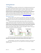
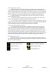
Table Of Contents
- Introduction
- Getting Started
- System Overview
- Operational Overview
- Initial Configuration
- System Menu Items
- Operation
- Fault Handling
- Wiring Diagrams
- Specifications
- Glossary
- Appendix 1: System menu overview
- Appendix 2: Organizing IDs in the CAN system
- Appendix 3: Ordering a system

Page 3
Rev 1.07 ©2015 Micro Air Corp 10/26/2015
Getting Started
CAN Bus Basics
The CAN system (Computer Area Network) is a communications protocol system
that facilitates communication between electronic controls. Controls are connected to
each other to form a network. Typical controls in a network could include ice makers,
chilled and heated water systems, air handlers, and direct expansion systems. The
physical connection is called a bus and consists of a minimum of two wires connected to
each device. Up to 127 controls including a computer connection may be connected on
one bus. CAN bus exchange protocol follow the ISO-11898 standard for CAN
specification 2.0 Part B. System integrators can find the message contents defined in the
Microair CAN protocol specification available from http://www.Microair.net.
Wiring the CAN bus
The bus consists of a two or three wire connection to each device in the system.
Wires are connected to each control in a sequentially wired, daisy chain style connection.
Wire used for the CAN bus must be rated as indicated in the specifications section of this
document.
To wire the system, first determine which devices will be at each end of the
system. All other devices will be connected between these two devices. Wire the bus
starting with a selected end device. Connect wires to CAN-L and CAN-H (and ground if
used) on this device then connect the other end of these wires to the second control in the
system. Connect wires in parallel to the wires connected to the second device to the third
device in the system. Continue making connections until all controls are connected.
Always connect GND to GND, CAN-L to CAN-L, and CAN-H to CAN-H. Never place
more than two wires in any terminal connection.
The control at each end of the bus must have a terminator installed. The
terminator is a two pin jumper located on the circuit board next to the CAN connector
labeled CT. Place this jumper only on the first and last control in your system.
During installation, write down the serial numbers of each device connected and a
description of the location they are in or are responsible for. This will help to simplify
system setup later.