
Hydromatic II Chiller Operation Manual
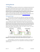
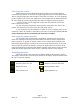
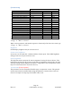
Table Of Contents
- Introduction
- Getting Started
- System Overview
- Operational Overview
- Initial Configuration
- System Menu Items
- Operation
- Fault Handling
- Wiring Diagrams
- Specifications
- Glossary
- Appendix 1: System menu overview
- Appendix 2: Organizing IDs in the CAN system
- Appendix 3: Ordering a system

Page 4
Rev 1.07 ©2015 Micro Air Corp 10/26/2015
Connecting the control
Make connections to the Hydromatic board as shown in the wiring diagram
contained in this manual. A freeze sensor, high refrigerant pressure switch, flow switch
and low refrigerant pressure switch must be connected to each slave. If a low refrigerant
pressure switch is not used in your application, a wire jumper must be installed between
the low refrigerant pressure signal connection and low refrigerant pressure ground.
If electric heater is used, a high limit sensor must be used with each electric
heater connected to a slave.
A return loop water temperature sensor must be connected to one slave in the
system. This sensor may be connected to any slave in the system.
If you are using a 24 volt transformer or other AC source to supply power to the
contactors, remove JP 14 and 15 and connect your source to the AUX terminals. Do not
connect anything to the AUX terminals with JP14 and 15 installed.
Connecting the pump controller
The separate pump control board is required for operation of the system. Sea
water flow switch FL1 and loop water flow switch FL2 must be used or bypassed for
proper operation. To bypass the switch, connect a wire from the GND terminal to the
switch being bypassed. FL2 is used for the sea water pump flow detection. FL1 is used
for the loop water pump flow detection. Connect the pump contactors as shown in the
pump wiring diagram contained in this manual. Optional water pressure sensors and the
optional sea water temperature sensor may be connected as shown in the diagram.
Navigating the menu
When the control is first powered, the display will show the firmware revision.
The display will then show icons along the bottom of the display. Press the button below
the icon to select the function.
___________ ________________________
Turn the system on or off. Advance to the next menu item.
Display the menu. Adjust parameter down.
Select a menu item. Adjust parameter up.