Retrofit Instructions Marvair Sea Mach™ To FX-2 System (OLED and EasyTouch Compatible) Micro Air Corporation 124 Route 526. AllentownNJ08501 Phone (609) 259-2636 WWW.Microair.
Introduction: Marvair Marine sold a number of “Sea Mach” controllers in the early years of production. These controllers are not available and no direct replacement for them exists. The following document outlines the steps necessary to retrofit the “Mach Air” style controller also known as an FX II into the original Sea Mach™ electrical box. This controller is produced by Microair corp. and is available as a kit that includes most of the parts needed to complete the installation.
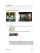
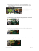
Rework Procedure: 1. Remove power from the system by turning off the breaker powering the system. 2. Open the electrical box and remove the power L1 and L2 connections from the large green connector. Use masking tape to label these connections as “AC Line”. Install a spade terminal on each wire. Ground Pump Power Display Air sensor 3. Disconnect the display cable. 4. Disconnect the air sensor cable and completely remove the air sensor from the system.
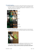
6. Disconnect the wires connected to the “Valve1” and “Valve2” terminals. Label the wires “Valve” using masking tape. Remove the existing connectors and install spade terminals on each of the wires. 7. Disconnect the wires from the “COMP3” and “CAPACOM1” terminals and splice them together. In some installations, the “CAPACOM1” wire can be removed and the “COMP3” wire connected directly to the run capacitor if wire length permits. 8. Disconnect the wire connected to the “COMP1” terminal.
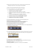
12. Disconnect the wire connected to the “FAN1” terminal and label it “FAN L1”using masking tape. Remove the existing connector and install a spade terminal on this wire. CAPAFAN2, FAN2, 20cm wire. CAPAFAN1, FAN 3 FAN1 13. Cut the wire from the plug connected to J3 that is closest to the “CAPAFAN2” terminal and splice it to the loose wire on the supplied connector. 14. Cut the center wire on the plug connected to J3 and splice it to the remaining outer wire on the supplied connector. 15.
16. Remove the coil sensor from J6 if one is connected. The coil sensor can be completely removed as it is not used in the new installation. 17. Remove the old board and install the FXII control board. 18. Connect the labeled wires to the terminal strip as follows: a. Connect the Fan L1 wire to FAN L1 terminal. b. Connect Fan L2 wire to FAN L2 terminal. c. Connect one of the valve wires to VALVE L1 terminal. d. Connect the second valve wire and one of the pump wires to PUMP L2 terminal. e.
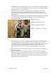
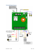
Finished Wiring Diagram November 17, 2015 7 Rev: 1.
Disclaimer 1. Microair has used reasonable care in preparing the information included in this document, but Microair does not warrant that such information is error free. Microair assumes no liability whatsoever for any damages incurred by you resulting from errors in or omissions from the information included herein. 2. The installer must exercise appropriate safety precautions when installing this product.