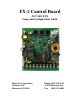
FX-2 Control Board ASY-360-XXX Setup and Configuration Guide Micro Air Corporation 124 Route 526. Allentown NJ 08501 Phone (609) 259-2636 WWW.Microair.
Table of Contents Introduction ......................................................................................................................... 4 Jumper settings................................................................................................................ 5 Systems with EasyStart ....................................................................................................... 6 Contactors .......................................................................................
Direct Expansion (DX) Wiring: Rev K PCB ............................................................ 19 Fresh Air Makeup Unit (FAMU) Wiring: Rev K PCB............................................. 20 EasyStart Wiring: Rev K PCB .................................................................................. 21 Rev L and M PCB ......................................................................................................... 22 Air Handler (AH) Wiring: Rev L and M PCB .................................
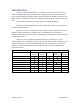
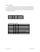
Introduction The FX-2 control board platform is a versatile control interface that supports a variety of displays and system configurations. Among the supported configurations are direct expansion (DX), air handler (AH), fresh air makeup unit (FAMU), EasyStart, and chiller control. The table below lists the compatible displays and the available options for each. DX and AH are hardware selectable options in compatible displays. FAMU is a software compatible option in compatible displays.
Jumper settings Hardware jumpers are provided on the FX-2 control board to provide additional functions. Printed circuit board (PCB) revision I and earlier have jumpers that must be set for proper display operation. Revision K and above automatically detect the display and do not have display setting jumpers. All boards have the configuration jumpers shown in the configuration table below. Display Selection (rev I and earlier PCB): JP9 JP11 Usage OLED OFF OLED OLED display. FX-MAXX ON FXMAX FXMAX display.
Systems with EasyStart Contactors Systems with compressors over 24K BTU or greater than 1.5 HP must use a contactor. See the wiring diagram for details. Capacitor Selection Best start performance, in most cases, can be achieved by using the start capacitor values found in the table below. BTU Rating Start Capacitor Size 37K to 48K 189 to 227uF 25K to 36K 130 to 156uF 12K to 24K 88 to 106uF 5K to 11K 64 to 77uF Run capacitors should be sized according to the compressor manufacturer’s recommendations.
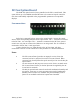
Additional EasyStart Jumper Usage The pin header JP1 on the EasyStart top board is used to configure EasyStart. The white block shown by the arrow one indicates pin number 1. Other pins are identified as shown in relation to pin 1. Caution: Do not place jumpers on JP1 except as indicated. Normal: Most operation should be done without a jumper installed on JP1 or with the jumper installed across pins 3 and 4.
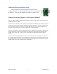
DC Fan Option Board The PCB-361 option board is factory installed on the FX-2 control board. This option allows up to four PWM controlled DC fans to be connected. Speed control for each fan is individually adjustable in the programmable parameters on compatible displays. Fan connections Each fan is connected by three wires to the control board. Connect the control wires to their corresponding terminals on the option board. The ‘+’ terminal is connected to the DC fans’ +10 volt output.
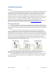
CAN Bus Systems Basics The CAN system (Computer Area Network) is a communications protocol system that facilitates communication between electronic controls. Controls are connected to each other to form a network. Typical controls in a network could include ice makers, chilled and heated water systems, air handlers, and direct expansion systems. The physical connection is called a bus and consists of a minimum of two wires connected to each device.
Wiring Diagrams Board and Firmware revisions This manual makes reference to FX-2 control board printed circuit board (PCB) revisions. The PCB revision is found along the edge of the printed circuit board in white silk screened lettering and starts with PCB-360. PCB-360-00J indicates a revision J circuit board. Firmware revision is marked on a label placed on the microcontroller integrated circuit on revision L circuit boards.
Using Contactors Circuitry on the board may adversely affect the operation of contactors by holding a contactor on when it should be off. This condition should be verified whenever a contactor is used by following the procedure below. WARNING: AC LINE VOLTAGE CAN BE DANGEROUS OR FATAL IF IMPROPERLY HANDLED. The following steps involve working directly with AC line power and must only be performed by trained service personnel. Checking Contactors 1. Disconnect the contactor load from the contactor. 2.
Using Solid State Relays (SSR) Circuitry on the board may adversely affect the operation of an SSR by holding an SSR on when it should be off. Customers with applications using an SSR should contact Microair prior to purchase for factory modification of the board. Boards may also be returned to Microair for modification. Using a Pump Relay with a Chiller The following information is provided for identification of modified boards.
Rev I and Earlier Air Handler (AH): Rev I and Earlier PCB January 4, 2019 13 Revision 1.
Direct Expansion (DX) Wiring: Rev I and Earlier PCB January 4, 2019 14 Revision 1.
Fresh Air Makeup Unit Wiring (FAMU) Rev I and earlier PCB January 4, 2019 15 Revision 1.
EasyStart Wiring: Rev I and Earlier January 4, 2019 16 Revision 1.
Chiller Rev I and Earlier January 4, 2019 17 Revision 1.
Rev K PCB Air Handler (AH) Wiring: Rev K PCB January 4, 2019 18 Revision 1.
Direct Expansion (DX) Wiring: Rev K PCB January 4, 2019 19 Revision 1.
Fresh Air Makeup Unit (FAMU) Wiring: Rev K PCB January 4, 2019 20 Revision 1.
EasyStart Wiring: Rev K PCB January 4, 2019 21 Revision 1.
Rev L and M PCB Air Handler (AH) Wiring: Rev L and M PCB (Rev M shown. Rev L has different style DC fan jack.) January 4, 2019 22 Revision 1.
Direct Expansion (DX) Wiring: Rev L and M PCB (Rev L shown. Rev M has different style DC fan jack.) January 4, 2019 23 Revision 1.
Fresh Air Makeup Unit (FAMU) Wiring: Rev L and M PCB (Rev M shown. Rev L has different style DC jack.) January 4, 2019 24 Revision 1.
EasyStart Wiring: Rev L and M PCB (Rev L shown. Rev M has different style DC fan jack.) January 4, 2019 25 Revision 1.
High Current and DC Fan Wiring: Rev L and M PCB (Rev L shown. Rev M has different style DC fan jack.) Note: Up to two DC fans can be connected to the DC fan output. January 4, 2019 26 Revision 1.
Chiller Control with EasyStart Rev L and M PCB (Rev L shown. Rev M has different style DC fan jack.) January 4, 2019 27 Revision 1.
Chiller Control Rev L and M PCB (Rev L shown. Rev M has different style DC fan jack.) January 4, 2019 28 Revision 1.
Specifications General Temperature sensor accuracy Low voltage limit 115 VAC units Low voltage limit 230 VAC units Line voltage limit Frequency Maximum board input current Minimum operating temperature Maximum operating temperature Maximum RH conditions (Board and display) Maximum length of the display cable Maximum length of the Outside air sensor cable Externally mounted heater or fan triac 2°F at 77°F 75VAC 175VAC 250VAC 50 or 60 Hz 30 Amps 0°F 180°F 95 % Non-condensing 75 Feet 50 Feet 16 Amps Applicat
Specifications (CONTINUED) Fresh Air Make Up Unit (FAMU) RH measurement range 5% to 100% Electric heater output: Rev I PCB and earlier (Connected to Fan L1 and L2) Rev J PCB and above: 16 Amps Maximum 16 Amp with external Triac Valve output MAX Fan output MAX Rev I PCB and earlier (Connected to Pump L1 and L2) Rev J PCB and above (Connected to Fan L1 and L2) 10 Amps Maximum 10 Amps Maximum 6 Amps Maximum 16 Amps with external Triac Display and Sensor Cable Flat (oval) multi-conductor shielded modular
COPYRIGHT © 2017 Micro Air Corporation, All Rights Reserved No part of this publication may be reproduced, translated, stored in a retrieval system, or transmitted in any form or by any means electronic, mechanical, photocopying, recording or otherwise without prior written consent by Micro Air Corporation. Every precaution has been taken in the preparation of this manual to insure its accuracy. However, Micro Air Corporation assumes no responsibility for errors and omissions.