
Coleman Mach Family RV A

Mach 8
17
©2022 Micro-Air Rev 1.09
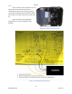
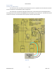
Disconnect the start capacitor
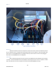
If your unit has a start capacitor is must be disconnected. Not all units have start capacitors so
first determine if your unit has one. Follow the red wire from the compressor into the electric box
(arrow 2 in Figure 23). If this wire leads to a PTCR (pointed to by arrow 3 in Figure 23) you have a start
capacitor that must be removed. If you do not have a start capacitor, you can continue to the next step
placing the orange wire.
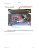
First locate the start capacitor. There may be up to 3 capacitors in this design. The metal case
capacitor (pointed to in Figure 23 arrow 5) is the “run capacitor”. If the unit has a start capacitor, it will
have a red and a yellow wire connected to it. If the unit has a fan capacitor, it has two brown wires
connected to it. Disconnect both red and yellow wires from the start capacitor. Follow the wires to the
other end of the wire. Disconnect and remove the wires.
Disconnect any remaining red wires from the compressor from the PTCR and remove the PTCR.
Reconnect the wires to the PTCR terminals on the connection block.
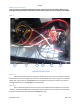
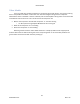
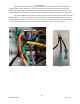
Orange wire
Install a female blue quick
connect on the ORANGE wire from
EasyStart. Verify that the red wire from
the compressor connects to the silver run
capacitor as shown in figure 24. If not,
disconnect the compressor red wire and
reconnect it to the group opposite the
yellow wires as shown by the red arrow.
Disconnect and remove any other red
wires on this group of terminals. Connect
the ORANGE EasyStart wire into one of
the open terminals as shown by the
orange arrow in figure 24.
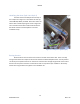
Black wire
Install a female blue quick connect on the BLACK wire from EasyStart. Connect it to an empty
terminal in the same group as the purple wire. (see Figure 23 arrow 6). Figure 23 arrow 7 points to a
barely visible extra terminal on the connection block where the black wire can be connected.
Figure 24