CONTENTS FX-1 Operations Manual Micro Air Corporation 124 Route 526 Allentown, NJ 08501 INTRODUCTION ......................................................................................................................................... 1 BASIC OPERATION .................................................................................................................................... 2 SYSTEM OVERVIEW ........................................................................................................
FX-1 Air Handler Control Operations Manual INTRODUCTION The FX-1 Air Handler Control is designed for use with Marine Chilled Water Air Conditioning Systems. FX-1 Air Handler Control has a universal power supply that operates on 115, 230, 50 or 60 Hz AC power. FX-1 Air Handler Control includes the following standard and optional features: Standard Features User friendly 4 button display panel requires no manual for basic operation. Five volt logic and micro controller located in the display.
FX-1 Air Handler Control Operations Manual BASIC OPERATION POWER BUTTON Press the power button once to toggle the unit to the on mode. Press the power button again to toggle the unit to the off mode. UP BUTTON Momentarily press and the set point will appear in the temperature display. The set point increases one degree each time the up button is pressed and released. DOWN BUTTON Momentarily press and release to display the set point.
FX-1 Air Handler Control Operations Manual OVERVIEW FX-1 Air Handler Control is a user friendly, easy to operate, programmable temperature control. Press the ON/OFF button once to engage the system. The display indicates room temperature when the system is on and the display is blank when the system is off. Press and release the Select Button until the desired Mode LED is illuminated. Set the room temperature by pressing the up or down button.
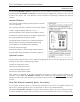
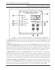
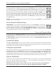
FX-1 Air Handler Control Operations Manual OPERATOR CONTROLS AND DISPLAY PANEL Refer to figure 1 for the buttons locations and display functions listed on the following pages. 1. POWER BUTTON The power button is used to toggle between the on and off modes. Press the power button once to toggle the unit to the on mode. Press the power button again to toggle to the off mode. 2. DOWN BUTTON Momentarily press and release the down button to display the set point.
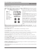
FX-1 Air Handler Control Operations Manual OPERATOR CONTROLS AND DISPLAY PANEL 5. COOL MODE LED The cool mode LED will be lit when the Cooling Mode has been selected. HEAT MODE LED The heat mode LED will be lit when the Heat Mode has been selected. The heat mode LED is also lit when the optional electric heat is installed and the heat mode is selected. Electric heater status, on or off, is indicated by the Operating LED. 6. Away Mode LED The Away Mode LED will be lit when the Away Mode has been selected.
FX-1 Air Handler Control Operations Manual MODES OF OPERATION Off Mode When the FX-1 Air Handler Control is in the off mode, all control outputs are turned off. Program parameters and user settings are saved in nonvolatile memory. The program mode can only be accessed from the off mode. The Ready LED remains lit in the off mode. On Mode When the control is in the on mode, power will be supplied to the appropriate control outputs and the display will indicate the current state of operation.
FX-1 Air Handler Control Operations Manual FAN MODE Automatic Fan Mode FX-1 Air Handler Control has six automatic fan speeds available. Speed six is high, three is medium and one is low or the slowest speed. Automatic fan mode allows the FX-1 Air Handler Control to determine the required fan speed based on room temperature. The closer the room temperature is to the set point, the slower the fan will run. This permits a balance between the most efficient temperature control and slower, quieter fan speeds.
FX-1 Air Handler Control Operations Manual ENTERING PROGRAM MODE The program mode can only be entered from the off mode. From the off mode and in the following order, press the Select, Up, Down and the Select buttons. These buttons have to be pressed and released in the order given. The letter "P" appears in the display. The buttons have to be pressed in the sequence described. Remember "SUDS"… It's the key to enter and unlock the program mode.
FX-1 Air Handler Control Operations Manual Programmable Parameters There are nineteen (19) programmable parameter locations with their Factory Default Settings listed in this section. The table below indicates what these parameters are, along with the permitted values and the original Factory Default Settings.
FX-1 Air Handler Control Operations Manual PROGRAMMING P-1: Fan Speed Automatic or Manual The program values allowed are A, followed by one (1) through six (6). Select "A" (factory default setting) for automatic fan speeds and the fan will operate in conjunction with room temperature. The further the room temperature is from set point, the faster the fan will run in the cooling mode.
FX-1 Air Handler Control Operations Manual P-10: Display Brightness Control The display brightness can be adjusted to suit ambient cabin lighting conditions. The allowed settings are four (4) to thirteen (13), with four (4) being the dimmest and thirteen (13) the brightest. Typically a dark cabin will require a setting of four or five. A very bright cabin will require a setting of twelve or thirteen. The factory default setting is thirteen (13).
FX-1 Air Handler Control Operations Manual P-16: Fan Motor Selection There are two basic fan motor types, shaded pole and split capacitor. Each motor reacts differently to speed control and each motor requires different timing for optimum fan speed variation. The default setting is "SC" which selects the split capacitor motor type, however, "SP" should be selected if a shaded pole type of fan motor is used in the system. Most air handlers are supplied with split capacitor type fan motors.
FX-1 Air Handler Control Operations Manual When equipped with an optional electric heater, the heater will overlap with the hydronic heat by twenty-two degrees Fahrenheit ( 22 ° F). The heater will turn on when heat is required and remain on until the hydronic water temperature exceeds the ambient by twenty-two degrees Fahrenheit or until the room temperature is satisfied. The electric heat is allowed to overlap the hydronic heat to supplement the main heating system during very cold conditions.
FX-1 Air Handler Control Operations Manual SPECIFICATIONS SET POINTOPERATING RANGE ............................................................................................ 55 ° F TO 85 ° F AMBIENT TEMPERATURE OPERATING RANGE DISPLAYED ..................................................... 55 ° F TO 85 ° F SENSOR ACCURACY .......................................................................................................... ± 2 ° F AT 77 ° F LOW VOLTAGE LIMIT 115 VOLT UNITS ...........................
FX-1 Air Handler Control Operations Manual Revision: 04 04/09/09 Page 15
FX-1 Air Handler Control Operations Manual Revision: 04 04/09/09 INSTALLATION OVERVIEW Page 16