Contents FX-1 Operations Manual Micro Air Corporation 124 Route 526 Allentown, NJ 08501 INTRODUCTION ........................................................................................................................................................... 1 BASIC OPERATION ...................................................................................................................................................... 2 SYSTEM OVERVIEW ....................................................................
FX-1 Operations Manual INTRODUCTION The FX-1 Control is designed for use with all direct expansion, reverse cycle air conditioning systems. FX-1 has a universal power supply that operates on 115, 230, 50 or 60 Hz AC power. FX1 includes the following standard and optional features: Standard Features User friendly 4 button display panel requires no manual for basic operation. Five volt logic and micro controller located in the display. 3-digit 7-segment display panel indicates °Fahrenheit or °Celsius.
FX-1 Operations Manual BASIC OPERATION POWER BUTTON Press the power button once to toggle the unit to the on mode. Press the power button again to toggle the unit to the off mode. UP BUTTON Momentarily press and the set point will appear in the temperature display. The set point increases one degree each time the up button is pressed and released. DOWN BUTTON Momentarily press and release to display the set point. The set point is decreased one degree each time the down button is pressed and released.
FX-1 Operations Manual OVERVIEW FX-1 is a user friendly, easy to operate, programmable temperature control. Press the ON/OFF button once to engage the system. The Display indicates room temperature when the system is on and the Display is blank when the system is off. Press and release the Select Button until the desired Mode LED is illuminated. Set the desired room temperature by pressing the up or down button. The set point can be viewed by momentarily pressing and releasing the Up or Down Button.
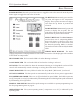
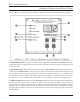
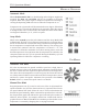
FX-1 Operations Manual OPERATOR CONTROLS AND DISPLAY PANEL Refer to figure 1 for the buttons locations and display functions listed on the following pages. 1. POWER BUTTON The power button is used to toggle between the on and off modes. Press the power button once to toggle the unit to the on mode. Press the power button again to toggle the unit to the off mode. 2. DOWN BUTTON Momentarily press and release the down button to display the set point.
FX-1 Operations Manual 4. SELECT BUTTON The select button is used to select one of the four operating modes. Press and release the select button and the FX-1 will advance to the next mode. Continue to press and release the select button until the desired operating mode is reached. The mode selected is indicated by the Mode LED, i.e., Cool, Heat, Automatic or Away Mode. 5. COOL MODE LED The cool mode LED will be lit when the Cooling Mode has been selected.
FX-1 Operations Manual SPECIAL BUTTON FUNCTIONS Special button functions are implemented by pressing and holding a particular button while the controls' AC power is turned on. 1. Service History Log… View the service history log by pressing and holding the select button while turning on the AC power. Exit the service history log by pressing the power button once. Clear the service history log by simultaneously pressing the power and down buttons. 2.
FX-1 Operations Manual MODES OF OPERATION Automatic Mode When the Automatic LED is on, both heating and cooling are supplied as required. The heat and cool LEDs will be lit according to the mode required. When the system requires compressor operation for heating or cooling the Operating LED will turn on when the compressor is on. Temperature in a given mode will be maintained at two degrees Fahrenheit ( 2 ° F ), however, a four degree difference is required to allow the control to change modes.
FX-1 Operations Manual PROGRAM MODE Program Mode Overview The program mode is used to adjust the systems operating parameters to suit the particular needs of individual users. The program mode is also used to tailor the air-conditioning system for the most efficient operation within an installation. Installation variables such as, ducting, sensor location and system layout effect the perceived operation of the overall system.
FX-1 Operations Manual USING THE PROGRAM MODE Increment from one program parameter to the next by pressing the select button while in the program mode. Press and release the select button to advance to the desired parameter. Use the up and down buttons to change the program parameter values. The programmable parameters range from P-1 through P-17. Up and Down Buttons The up and down buttons are used to select the data or set the desired limits for the parameter being programmed.
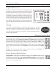
FX-1 Operations Manual Programmable Parameters There are seventeen (17) programmable parameters with their Factory Default Settings listed in this section. The table below indicates what these parameters are, along with the permitted values and the original Factory Default Settings.
FX-1 Operations Manual P-2: High Fan Limit The upper fan speed limit can be tailored to suit various motors and operating conditions. The high fan limit is adjusted with the system installed and operational. The range of values are 56 through 85 and represent arbitrary units. Setting a higher number, results in a higher fan speed, setting lower numbers, lowers the high fan speed limit. Use the up and down buttons to select the desired high fan speed limit. The factory default setting is eighty-five (85).
FX-1 Operations Manual P-8: De-Icing Cycle FX-1 is equipped with a De-Icing Cycle to prevent ice build up on the evaporator coil during extended periods of cooling operation. Installation variables such as grille sizes, length of ducting, insulation R factors and ambient temperatures determine the cooling run time required to achieve set point. Customer usage may substantially increase run times by operating the system with the hatches and doors open.
FX-1 Operations Manual P-14: Cycle Fan with Compressor The fan can be programmed to run continuously when the system is on or can be allowed to cycle with the compressor. When cycled with the compressor, the fan will operate only when heating or cooling is called for. To cycle the fan with the compressor select CYC which stands for cycle the fan with the compressor. To operate the fan continuously select con which represents continuous fan operation.
FX-1 Operations Manual FAIL-SAFE AND FAULT HANDLING CODES LAC… Indicates low AC line power AAA… Indicates failed air sensor. Unit will not run until repaired. PPP… Indicates the sea water pump has failed. Fail-Safe There are four levels of fail-safe protection including the fail-safe off mode. Level one monitors the sensors, takes appropriate action and allows continuous restarts after a 90 second delay… Does not display the fault code.
FX-1 Operations Manual AUTOMATED FACTORY-SELF TEST PROGRAM Self-Test Mode The FX-1 software contains a self-test program to facilitate factory testing of the entire airconditioning system. Once the self-test mode is activated, the test cycle will continue until the AC power is interrupted or the on/off button is pressed once which returns the system to the off mode. Activate the self-test by pressing and holding the on/off button while turning on the AC power.
FX-1 Operations Manual DIMENSIONS DISPLAY PANEL ................................................................................................................ 3.75" X 3.75" PANEL CUT OUT ............................................................................................................ 3.150" X 3.150" CABLE LENGTHS SELF CONTAINED DISPLAY CABLE .......................................................................................... 15' STANDARD CENTRAL SYSTEM DISPLAY CABLE ....................
FX-1 Operations Manual SERVICE TOOLS Hour Meter Total compressor cycle time is saved in EEPROM every 6 minutes of continuous compressor running time. Cycles less than 6 minutes will be discarded to conserve memory and allow the most flexible hour-meter possible. To view the hour meter turn off the power at the AC breaker and hold the down button depressed. While depressing the down button, restore AC power. After the Power-On reset routine is complete, the following will appear in the display: 1.
FX-1 Operations Manual Revision: 06 04 / 08 / 09 FX-1 WIRING DIAGRAM Page 18
FX-1 Operations Manual Revision: 06 04 / 08 / 09 INSTALLATION OVERVIEW Page 19