AirNet CAN Bus Implementation Revision 8.
Table of Contents 1. CAN Implementation ........................................................................................................................ 3 2. Standard Data Types ........................................................................................................................ 4 3. HVAC Command 0x3F0 (1008.) ..................................................................................................... 5 4. HVAC Status 0x3E0 (992.) ..................................
Index 1. CAN Implementation The can data rate of 250K is to be used. 1.1 Message Arbitration (CAN ID) Micro Air messages using the CAN protocol shall use 29-bit IDs as follows: ...p ppii iiii iiii ssss ssss dddd dddd (29-bit binary CAN ID) or ...p ppii iiii nnnn nnnn nnnn nnnn nnnn (29-bit binary CAN ID) p = Priority Field (0..
Index 2. Standard Data Types This section defines standard data types. They are documented here so that each individual message need not re-define the types. 2.1 Bit Field Types bits8, bits16, bits32 Note: Bit fields can be of any length, they are not required to be 8, 16, or 32 bits long. 2.2 Unsigned Integer Types uint8, uint16, uint32 Note: Unsigned integers can be of any length, they are not required to be 8, 16, or 32 bits long. 2.
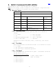
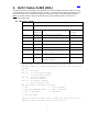
Index 3. HVAC Command 0x3F0 (1008.) This message is used to send the HVAC unit a command. Note: For all fields, a value of 0xFF for 8 bits indicates a supported field for which no information is available (ex faulted input). 3.1 Message Content CAN ID ...
For device ID 0x378 & 0x386: 6 Fan Speeds Index 0 = No Change 1 - Off or Auto 2 – Manual Speed 1 3 - Manual Speed 2 4 - Manual Speed 3 5 - Manual Speed 4 6 - Manual Speed 5 7 – Manual Speed 6 8-0xFE = Manual Speed 6 For device ID 0x505 and 0x560: 5 Fan Speeds 3 Fan Speeds 0 = No Change 0 = No Change 1 - Off or Auto 1 – Off or Auto 2 – Manual Speed 1 2 – Manual Speed 1 3 - Manual Speed 2 3 – Manual Speed 2 4 - Manual Speed 3 4 – Manual Speed 3 5 - Manual Speed 4 5-0xFE = Manual Speed 3 6 - Ma
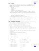
Index 4. HVAC Status 0x3E0 (992.) The HVAC unit sends this message for two purposes. The first is for display information, and the second is to acknowledge an HVAC Command message. Therefore, it is broadcast in two ways: periodically at a rate not less than once every 10 seconds and asynchronously upon receipt of a HVAC Command message. Note: For all fields, a value of 0xFF for 8 bits indicates a supported field for which no information is available (ex faulted input). 4.1 Message Content CAN ID ...
Index 4.1.2 Status This field further specifies the operating mode. A display unit may use this message to determine whether or not the heater (bit 0) or chiller (bit 1) is actually operating at this time in the case of automatic operating mode. 7: Reserved 6: Condenser Fan3 5: Generator3 4: DX Aux Heater1 On or Heater 23 On 3: Lockout. (Any fault flashing continuously) To remove the lock out and resume normal operation the fault must be corrected then the unit must be turned off and back on.
7 - Auto Fan off 7 - Auto Fan off 8 - Auto Speed 1 8 - Auto Speed 1 9 - Auto Speed 2 9 - Auto Speed 2 10 - Auto Speed 3 10 - Auto Speed 3 11 - Auto Speed 4 11 – n/a 12 - Auto Speed 5 12 – n/a 13 – Auto Speed 6 13 – n/a For device ID 0x505 or 0x560: 5 Fan Speeds 3 Fan Speeds 0 - Off 0 - Off 1 – Manual Speed 1 1 – Manual Speed 1 2 - Manual Speed 2 2 – Manual Speed 2 3 - Manual Speed 3 3 – Manual Speed 3 4 - Manual Speed 4 4 – Auto Fan off 5 - Manual Speed 5 5 – Auto Speed 1 6 - Aut
Index Faults 4.1.7 This bit field indicates the current fault status. The three-letter pneumonic in parentheses is the corresponding fault shown on the control’s display. See the control’s operations manual for more details.
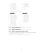
Index 5. HVAC Supplemental Status 0x3FF 1023.) 5.1 Message Content CAN ID ...p pp11 1111 1111 ssss ssss dddd dddd Data Size Data Data[0] 7 Bits Description 76543210 0 Scale / Format Page Data[1] XXXXXXXX Voltage uint8 Data[2] XXXXXXXX Current uint8 Data[3] XXXXXXXX Fan A Duty Cycle uint8 Data[4] XXXXXXXX Fan B Duty Cycle uint8 Data[5] XXXXXXXX Fan C Duty Cycle uint8 Data[6] XXXXXXXX Fan D Duty Cycle uint8 Data[7] XXXXXXXX Triac simulation = 0x00, PWM = 0x55 uint8 5.1.1 5.1.
Index 5.2 Message Content CAN ID ...p pp11 1111 1111 ssss ssss dddd dddd Data Size 7 Data Bits Description 76543210 Data[0] 1 Scale / Format Page Data[1] XXXXXXXX BTU request int8 Data[2] XXXXXXXX Humidity (Supply) uint8 Data[3] XXXXXXXX Humidity (outside) uint8 Data[4] XXXXXXXX Humidity Setpoint uint8 Data[5] XXXXXXED Daughterbrds installed enum8 Data[6] XXXXXXXX EasyStart Peak Current uint8 Data[7] XXXXXXXX EasyStart Run Current 5.2.1 5.2.
Index 6. HVAC Fan Slave Status 0x3EF (1007.) 6.1 Message Content CAN ID ...p pp11 1110 1111 0000 0000 dddd dddd Data Size 2 Data Bits Description 76543210 Scale / Format Data[0] XXXXXXXX Status bit Data[1] XXXXXXXX Fan A Duty Cycle uint8 6.1.1 Status Bit 0 = fan on Bit 1 = Trouble Bit 2 = Hot. 6.1.2 Fan A Duty Cycle The duty cycle for Fan A.
Index 7. Icemaker Command 0x3F1 (1009.) 7.1 Message Content CAN ID ...p pp11 1111 0001 dddd dddd ssss ssss Data Size Data 1 Bits Description 76543210 Data[0] XXXXXXXX State 7.1.1 Scale / Format enum8 State The lower nibble is defined as follows: 0 – no change 1 – Off 2 – On 8. Icemaker Status 0x3E1 (993.) 8.1 Message Content CAN ID ...
Index 1: Compressor On 0: Auger On 8.1.3 Faults This 8 bit enumerated field indicates the current fault status. The three letter pneumonic in parentheses is the corresponding fault shown on the control’s display. See the control’s operations manual for more details.
Index 9. Hydromatic System Command 0x3F2 (1010) 9.1 Message Content CAN ID ...p pp11 1111 0010 dddd dddd ssss ssss Data Size 2 Data Bits Description 76543210 Scale / Format Data[0] XXXXXXXX State byte Data[1] XXXXXXXX Lockout override bit 9.1.1 State The lower nibble is defined as follows: 0 – no change 1 – Off 2 – Cool 3 – Heat 4 - Auto 9.1.2 Lockout override Bit position when set will clear fault count and lockout at the slave.
Index 10. Hydromatic System Status 0x3E2 (994.) The Hydromatic sends this message for two purposes. The first is for display information, and the second is to acknowledge a Hydromatic Command message. Therefore, it is broadcast in two ways: periodically at a rate not less than once every 10 seconds and asynchronously upon receipt of a Hydromatic Command message. Note: For all fields, a value of 0xFF for 8 bits indicates a supported field for which no information is available (ex faulted input). 10.
Index 10.1.2 Mode Bit 0 – system mode B1:B0 =00 cool 01=heat 10=auto Bit 1 – system mode Bit 2 – Electric Heat mode Bit 3 – Cycle in progress Bit 4 – Pump Trouble Bit 5 – Power Bit 6 – Sea water pump on Bit 7 - Chilled water pump on 10.1.
Index Bit 0: stage 1 enabled Bit 4: stage 5 enabled Bit 1: stage 2 enabled Bit 5: stage 6 enabled Bit 2: stage 3 enabled Bit 6: stage 7 enabled Bit 3: stage 4 enabled Bit 7: stage 8 enabled 10.1.11 Stage Trouble Identifies slaves that currently have an active fault. 10.1.12 Compressors at reduced speed Identifies slaves that are running at a reduced speed. 10.1.13 Compressor speed Speed compressors identified by previous item are running at in 1/256ths of full speed.
Index 11. Hydromatic Slave Status 0x3E3 (995) 11.1 Message Content CAN ID ...
Index 11.1.1 Freezestat Temperature This is the circulating water temperature at the compressor output in Fahrenheit. 11.1.2 Return water Temperature This is the circulating water temperature at the heater output in Fahrenheit. This sensor is optional and should only be installed on the master stage. A value of 0xff will be transmitted if not installed. 11.1.3 High limit Temperature This is the circulating water temperature at the heater output in Fahrenheit.
Index 12. Generic Command 0x30n (768-783) 12.1 Message Content CAN ID ...
Index Device Page 0 Page 1 251 (pump) Transducer bit0=cir. Pump range bit1=sea pump unit ID bit5=comp 360 (HVAC) bit6=valve bit7=pump 851 (QuietFan) unit ID 12.1.7 Device/page defined byte 1 On page 0 this value will be used by the unit to set its group Id. On page 1 this is the first control byte. (See specific device type for further definition) Device Page 0 Page 1 251 (pump) Transducer offset 360 (HVAC) Undefined fan speed 851 (QuietFan) group ID 12.1.
Index 13. Pump Status 0x3E4 (996) 13.1 Message Content CAN ID ...p pp11 1110 0100 ssss ssss dddd dddd Data Size n Data Bits 76543210 Description Scale / Format Data[0] XXXXXXXX Page Uint8 Data[1] XXXXXXXX Data Byte 1 Data[2] XXXXXXXX Data Byte 2 Data[3] XXXXXXXX Data Byte 3 Data[4] XXXXXXXX Data Byte 4 Data[5] XXXXXXXX Data Byte 5 Data[6] XXXXXXXX Data Byte 6 Data[7] XXXXXXXX Data Byte 7 13.1.1 Page 0 This byte identifies the page number.
Index 13.1.2 Page 1 This byte identifies the page number. Page 1 only transmitted when configured as a modulated compressor control. 13.1.2.1 Data Byte 1 (Status) This is a bit defined field representing hardware status. Bit order is FTPMABSC.
Index 14. Ping 0x200 (512.) Used to determine presence of a device. When the global destination address of 00 is used all units in system will respond. Similarly group numbers can be used for units for the destination address. This will give an indication of addresses used by the units, which have power applied. Used in conjunction with Ping with serial number and address change it can also be used to resolve address conflicts. 14.1 Message Content CAN ID ...
Index 16. Ping response 0x22n (544 – 559) 16.1 Message Content CAN ID ...p pp10 0010 nnnn nnnn nnnn nnnn nnnn Data Size 6 Data Bits Description 76543210 Scale / Format Data[0] XXXXXXXX Unit ID Byte Data[1] XXXXXXXX Group ID Byte Data[2] XXXXXXXX Device ID Hex Data[3] XXXXXXXX Device ID Hex Data[4] XXXXXXXX Boot Revision ASCII Data[5] XXXXXXXX Code Revision Byte 16.1.1 nnnn nnnn nnnn nnnn nnnn This is the lower six digits of the unit’s serial number in hex. 16.1.2 Unit ID Units ID.
Index 17. Address change 0x230 (560.) 17.1 Message Content CAN ID ...p pp10 0011 0000 dddd dddd ssss ssss Data Size 5 (6) Data Bits 76543210 Description Scale / Format Data[0] XXXXXXXX New address Byte Data[1] XXXXXXXX Serial # Byte Data[2] XXXXXXXX Serial # Byte Data[3] XXXXXXXX Serial # Byte Data[4] XXXXXXXX Serial # Byte The serial number must match the serial number of the unit the message is intended for.
Index 18. Group address change 0x240 (576.) 18.1 Message Content CAN ID ...p pp10 0100 0000 dddd dddd ssss ssss Data Size 1 Data Bits 76543210 Description Scale / Format Data[0] XXXXXXXX New Group Byte This command will change the group the unit is assigned to. 18.1.1 New Group Assignment New value to be used as the group address of the unit. 19. Address change response 0x250 (592.) 19.1 Message Content CAN ID ...
Index 20. Silent mode 0x260 (608.) 20.1 Message Content CAN ID ...p pp10 0110 0000 dddd dddd ssss ssss Data Size 1 Data Bits 76543210 Description Data[0] XXXXXXXX 01/00 Scale / Format 20.1.1 Silent Mode Flag 0 – Normal mode. All communication messages allowed. will report status once every 10 seconds. Unit 1 – Only silent mode response message allowed. Unit will report its current state before switching to silent mode.
Index 22. Read Memory 0x285 (645.) 22.1 Message Content CAN ID ...p pp10 1000 0101 dddd dddd ssss ssss Data Size 3 Data Bits 76543210 Description Scale / Format Data[0] XXXXXXXX Hex Data[1] XXXXXXXX Data[2] XXXXXXXX High byte of starting address low byte of starting address Number of bytes 22.1.1 Starting address First byte of data range requested. 22.1.2 Number of bytes Number of bytes to read.
Index 23. Read Memory Reply 0x286 (646.) 23.1 Message Content CAN ID ...
Index 24. EE Memory Reply 0x289 (649.) 24.1 Message Content CAN ID ...
Index 25. Eeprom Write 0x287 (647.) 25.1 Message Content CAN ID ...p pp10 1000 0111 dddd dddd ssss ssss Data Size Data 3 Bits Description 76543210 Scale / Format Data[0] XXXXXXXX High byte of address XXXXXXXX low byte of address XXXXXXXX data Hex Data[1] Data[2] Hex HEX 25.1.1 Address Address of data to be written. 25.1.2 Data Data. 26. Eeprom Read 0x288 (648.) 26.1 Message Content CAN ID ...
Index 27. Eeprom reply verbose 0x28A (650.) 27.1 Message Content CAN ID ...p pp10 1000 1000 dddd dddd ssss ssss Data Size Data n Bits 76543210 Description Scale / Format Data[0] XXXXXXXX Page 0 of 7 Hex Data[1] XXXXXXXX Index Hex Data[2] XXXXXXXX Number of Parameters Hex Data[3] XXXXXXXX Length of Parameter Hex Data[4] XXXXXXXX Multiplier Hex Data[5] XXXXXXXX Default bits 23-16 Hex Data[6] XXXXXXXX Default bits 15-8 Hex Data[7] XXXXXXXX Default bits 7-0 Hex CAN ID ...
Index CAN ID Data Size Data ...p pp10 1000 1000 dddd dddd ssss ssss n Bits 76543210 Description Scale / Format Data[0] XXXXXXXX Page 2 of 7 Hex Data[1] XXXXXXXX Ascii Data[2] XXXXXXXX Data[3] XXXXXXXX Data[4] XXXXXXXX Data[5] XXXXXXXX Data[6] XXXXXXXX Data[7] XXXXXXXX Item Description byte 1 Item Description byte 2 Item Description byte 3 Item Description byte 4 Item Description byte 5 Item Description byte 6 Item Description byte 7 Ascii Ascii Ascii Ascii Ascii Ascii CAN ID ...
Index Data[4] XXXXXXXX Item Description byte 11 Ascii Data[5] XXXXXXXX Item Description byte 12 Ascii Data[6] XXXXXXXX Item Description byte 13 Ascii Data[7] XXXXXXXX Item Description byte 21 Ascii CAN ID ...
Index Data[4] XXXXXXXX Item Description byte 24 Ascii Data[5] XXXXXXXX Value Description byte 1 Ascii Data[6] XXXXXXXX Value Description byte 2 Ascii Data[7] XXXXXXXX Value Description byte 3 Ascii CAN ID ...
Index Data[3] XXXXXXXX Ascii Data[4] XXXXXXXX Ascii Data[5] XXXXXXXX Ascii Data[6] XXXXXXXX Ascii Data[7] XXXXXXXX Ascii 27.1.1 Page n of 7 Upper nibble is number of pages in reply. page number. Lower nibble is 27.1.2 Index Index of parameter requested. 27.1.3 Number of parameters Total number of parameters in product. 27.1.4 Length of parameter Number of bits in parameter. 27.1.5 Multiplier Used to increase value range. 27.1.6 Default Value Parameter default value.
Index 28. Download CAN firmware 0x1AA (426.) This is a variable length multi page message. 28.1 Message Content CAN ID ...p pp01 1010 1010 dddd dddd ssss ssss Data Size 8 Data Bits 76543210 Description Data[0] XXXXXXXX Page n of n Data[1] XXXXXXXX Starting high address Data[2] XXXXXXXX Starting low address Data[3] XXXXXXXX String Data[4] XXXXXXXX String Data[5] XXXXXXXX String Data[6] XXXXXXXX String Data[7] XXXXXXXX String Scale / Format 28.1.
Index 29. Transmission Error 0x0FF (255.) This may be generated during downloading. If received during downloading the download should be aborted and retried from the beginning. Failure to do this will cause the unit to operate improperly. 29.1 Message Content CAN ID ...p pp00 1111 1111 ssss ssss dddd dddd Data Size Data 2 Bits Description 76543210 Scale / Format Data[0] XXXBSCFA MOB ERRORS Bits8 Data[1] XXXXXXXX DOWNLOAD Error number Byte Data[2] XXXXXXXX Flash Page Address Byte 29.1.
Index 30. Flash Write Ready 0x1AB (427.) This is generated during downloading at the end of each successful write. 30.1 Message Content CAN ID ...p pp00 1111 1111 ssss ssss dddd dddd Data Size 0 31. Wiring Connect the CAN-H to the CH terminal and the CAN-L to the CL terminal, and ground (shield) to GND on each of CAN bus adaptor devices. Use twisted pair cable (CAN-H and CAN-L on one pair) with a shield for best results.