7 N\ ECU-Max Operations Manual 3 cool oer O Ic Most Ire — CONTROL FAN | J Amo SDE [1 SET POINT AJAR SYSTEMS INE Al /RAVINE AIR Systems @ A Member of the Taylor Made Group,, > J VER: 10a 12/97
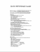
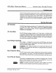
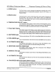
QUICK REFERENCE GUIDE Is » sophisticated solid-state control used to operate marine ECU-M axx VAC systems. It incorporates a menu for user programmable parameters and non-volatile memory to retain all settings. This quick reference guide provides information on basic operation, view modes and fault codes. For Marc information refer to the ECU-Max Manual, OPERATION: 1. Press POWER button to turn the system ON and OFF. 2. Press MODE button to select; AUTO Automatic cooling and heating modes.
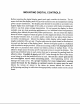
MOUNTING DIGITAL CONTROLS Before mounting the digital display panel touch pad, consider the location. The air sensor built into the display panel will provide excellent room air temperature sensing given a proper installation. The display panel should be mounted on an inside wall, slightly higher than mid-height of the cabin, in a location with freely circulating air where it can best sense average temperature.
ECU-Max Operations MANUAL Table Of Contents INTRODUCTION rear a SOSes nee 2 SYSTEM FEATURES .evergreen 2&3 Soup State FUSING... cu... OPERATOR CONTROLS & Laddish PANEL woornvisracrenanns Moses or Ope Ration [Au To, Cool, Heat & Moisture Control] Fan TN Using THE ECU-MAX ..oversensitiveness View Mode .. — Pro Gram MODE. J rennin Restoring Factory DEFAULT SETTINGS Leeriness eases nen Reverse Auto Fan OPERATION IN HEAT MODE ...
ECU-Max Operations Manual INTRODUCTION * SYSTEM FEATURES INTRODUCTION The ECU-Max (Environmental Control Unit) is a full featured reverse cycle heat tempura controller for marine VAC. The unit consists of one display control head and a remote high voltage system control module. The system has been designed for easy installation and solid state operation.
ECU-Max Operations Manual System FEATURES Ambient Light Sensor The display panel is equipped with an ambient light sensor (photo diode) which automatically controls the display brightness. This feature allows maximum visibility in very bright conditions while maintaining adequate but subdued brightness in the dark. Non-Volatile PROMOTE Memory Operating and programmed parameters are entered into nonvolatile memory.
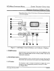
ECU-Max Operations MANUAL System FEATURES * DISPLAY PANEL OPERATOR CONTROLS & Dis Play PANEL Please refer to Figure 1, below, for the location of the buttons and displays listed on the following pages: po INSIDE OUTSIDE | CI] SET POINT foes Figure 1: ECU-Max Control Buttons and Indicator Displays 1.
ECU-Max Operations Manual Operator Controls & Display Pane 4. DOWN button The Down button is used to decrease the temperature set pant value, and to decrease the value of programmable parameters when the ECU-Max is in Program Mode. 5. MODE button The Mode button is used to switch between the various modes of operation of the ECU-Max. The modes are AUTO, HEAT, COOL and MOISTURE CONTROL. This button is also used to stroll up through the programmable features in Program Mode. 6.
ECU-Max Operations MANUAL Dis Play Panel » Moses oF OPERATION 15. INSIDE AIR TEMPERATURE light When the Inside Air Temperature indicator LED is lit, the 3-digit display will provide a readout of the inside air temperature as detected by the inside air sensor (located on the face plate unless the alternate air sensor is installed). 16.
ECU-Max Operations Manual Moses oF Operation is required to establish demand. A 4° shift is required to change from one mode to the other. Once tile required heating or cooling mode has been established, the hysteresis remains 2°, Moisture Control Mode When the ECU-Max is configured for Moisture Control Mode, the system maintains a preset temperature and humidity range. These ranges are programmable.
ECU-Max Operations Manual Using THe ECU-Max Selecting Heat Only Mode Repeatedly press the Mode button until the Heat Mode indicator LED is on, and heating will be supplied when required. Nate: If the water temperature is below the low water limit, the valve and compressor will turn off and heat will be supplied by the optional CAL rod heater, if installed.
ECU-Max Operations Manual Using THE ECU-Max The maximum temperature differential may be increased from changing the programmable parameter Automatic Fan Speed Spread. The increase in the spread from 6° to 12° results in one fan speed reduction for every 2° decrease in temperature. When programmed in this mode, high fan speed is used only in extremely hot conditions. Once the room is cooled down, conditions requiring high fan speed are less likely to recur.
ECU-Max Operations Manual Using THE ECU-Max I. AC Line Voltage (Voltmeter) (code "AC"} 2. AC Amperage (Ammeter) (code "cur’) 3. Water Sensor (code "H20") 4, Total Compressor Run Time (in hours) (code "ert™) 5. Freon Low Pressure (code 6. Freon High Pressure (code 7. AC Line Frequency (code "Free) Exit View Mode by pressing the Temp Select Button. This will return the unit to normal operation. The ECU-Max will exit View Mode automatically if no buttons are pressed for 1 (one) minute.
ECU-Max Operations MANUAL Using Program Mode The program parameters are displayed by pressing the Mode button or the Temp select button. Program parameters are designated by "P-n" in the display, where "un" is a number from | to 34. Pressing the Mode button repeatedly will cause the display to scroll up through all the program parameters. Pressing the Temp Select button will cause the display to scroll down through all the program parameters.
ECU-Max Operations Manual P-2: Moisture Control Mode High Temp Set Point This function sets the minimum cooling temperature that will be maintained in 0B Moisture Control Mode. The range for this value is between 95°F and 77°F The room temperature where the ECU-Max display panel is located (unless a remote air Temp. Sensor has been installed) will not be allowed to exceed the temperature selected by this set point. Use the Up and Down buttons to select the temperature.
ECU-Max Operations Manual Programmable PARAMETERS P-8: High Fan Speed Limit The upper limit of the fan speed can be reduced to tailor the fan output for various motors. The range of values for the high fan speed are 50 through 80 in arbitrary units. The high fan limit is not permitted above 220 VAC to prevent excessive fan noise. Use the Up and Down buttons to select the fan speed preset. The factory default setting of this function is 70.
ECU-Max Operations Maniac PROGRAMMABLE PARAMETERS P13: High Water Limit The high water limit defines the availability of cooling water for the condenser coil. The water pump and compressor are not allowed to operate above the high water limit. High water temperatures at the condenser inlet usually indicate a lack of cooling water. Temperatures at or above the high water limit are indicated by alternately flashing "H-I" and then "H20" in the display. Fail-safe protection levels apply to the high water limit.
ECU-Max Operation S MANUAL PROGRAMMABLE PARAMETERS P18: High Pressure Freon Switch Disable This option has been provided to disable High Pressure Faults in heating mode only, since high head pressure can be an acceptable occurrence while heating. This function is only valid if P16 is enabled. P19: Low Pressure Freon Switch Hold-Off Delay Low Freon pressure conditions can occur during normal operation. To prevent erroneous LP faults from occurring a hold-off delay is provided.
ECU-Max Operations Manual PROGRAMMABLE PARAMETERS ON A continued low line voltage condition for 5 minutes wiki cause the compressor to turn off while the fault code "LO-AC" flashes with the line voltage in the display. After 4 successive failures the system requires a manual restart.
ECU-Max OPERATIONS Manual Programmable PARAMETERS P27: Soft Start Ramp Delay P28: Self Test The diagnostic The compressor soft start feature is 2 factory-installed option on the Cecum, developed to reduce the electrical loading placed on the system when the compressor starts up.
ECU-Max Operations MANUAL PROGRAMMABLE PARAMETERS P30: Station ID Number Used to identify the control's placement when connected with the LAN-Maxx network option. P31: Internalization System Option This option is used when there is no sea water available. With this option ON, the sea water pump is disabled and Heat is provided by an Electric Heater ONLY.
ECU-Max Operations MANUAL Factory Default Taste 8 Programmable Parameter er Permitted Values or Ranges P-1 | Moist Cart Moro Humidification Level Level 1 L203 P-2 | Moist Cruet Mode High Temp Set Foi BF TI 10 95°F 123°C 10 35°C P-3 | Moist CRT More Low Temp Set Point ss 50°F 10 69 pd pint Cor Cs Cocks With Comp. On = Pup w/ Comp. ote Canto ren ) P-5 | Temperature Display Temperature Calibration (Used fo Cat.
ECU-Max Operations MANUAL THEORY OF OPERATION RR A eee THIEVERY OF LIBERATION ECU-Max System Timing Timed Start Timing Soft Start Timing The following discussion explains the steps the ECU-Max control takes at the beginning of a heating or cooling cycle. There are two different start-up protocols: timed start and soft start. Soft start has been developed to reduce the starting load placed on the electrical system by the compressor. It is an optional feature and must be installed by the factory.
ECU-Max Operations Manual System Inputs AND Outputs Internal Sensor Inputs The ECU-Max has four internal sensors: 1. Control Panel Air Temperature Sensor 2. Control Paine Ambient Light Sensor 3. AC Line Voltage 4. System Amperage External Sensor Inputs System Outputs FAN PUMP VALVE COMP. HEATER START RELAY The standard ECU-Max has inputs for three external sensors. Please refer to Figure 3 for a graphic representation of where these inputs are, 1. Alternate Air / Outside Air Temperature Sensor 2.
ECU-MAX MANUAL SUPPLEMENT RE: LOW PRESSURE SWITCH WIRING Effective with ECU-Max version 45 the low-pressure switch connection terminals on the board have been reversed. The top terminal is now the connection to be used for the low-pressure lead. The bottom terminal is now the common leg, which is connected through the board trace to the high-pressure common terminal. When connecting a version 45 ECU-Max the low-pressure switch blue wire must be attached to the top LP switch terminal.
Airfare AND Fa Ult Handling ECU-Max Operations Manual PAGE 24 Fault Code Action Taken by ECU-Max Level Level 2 | Level 3 Air Sensor Fault AIR [Complete shutdown until the fault is cleared. YZS YES YES Water Sensor Fault H20 {shutdown of water pump unl the fault is cleared. MO YES YES High Pressure Fault | H-P |Shutdown of compressor until the faults cleared. MO YES YES Low Pressure Fault L-P |Shutdown of compressor until the fault is cleared. MNO YES YES Sustained Low 1-0 nitwit continue to operate.
ECU-Max Operations Manual Fail-Safe Lockout Fault Display FAULT HANDLING & FAIL-SAFE MODES There are three levels of fail-safe protection, Level 1 is the lowest. In this level, the sensors are not monitored for faults. In the two other levels, the sensor is monitored for faults. In level 2, if'a fault is detected, the fault code is displayed, but no other action is taken. In level 3, the fault is displayed and the compressor is shut down.
ECU-Max Operations Manual 416 Oration Boar Rd An Optional Accessory Board may be ordered for the ECU-Max [Part Number: 416-X0A].
ECU-Max Operations MANUAL SPECIFICATIONS SET POINT RANGE DISPLAY TEMP RANGE LOW VOLTAGE DETECTION Programmable SENSOR ACCURACY FUSING VOLTAGE FAN OUTPUT VALVE PUMP COMPRESSOR CAL ROD HEATER (416 Option Board Required) 60° F to 85°F ZERO (0) to 160° F 115 VOLT UNITS 85 VAC 220 VOLT UNITS 185 VAC +2°F at 77°F ELECTRONIC 110 or 220 VAC SNIPS at 220 VAC 25 AMPS at 220 VAC 25 AMPS at 220 VAC 40 AMPS at 220 VAC 30 AMPS at 220 VAC ECU-Max Verbena 12/1/97 PAGE 28
ECU-Max Operations Manual Factory Programming Options F-1 Through F-8 Enter the factory program mode by first entering the programming mode then pressing the power and fan buttons simultaneously. Use the mode button to move forward and the Temp select button to scroll back through the factory program items. Once in the factory mode the following program changes can be made: F-1: Voltage Calibration The systems volt meter can be adjusted plus or minus 10 volts AC. Use this item to calibrate the voltmeter.
/VITRINE AIR Systems 2000 NORTH ANDREWS AVENUE EXTENSION POMPANO BEACH, FLORIDA 33069-1497 U.S.A. Telephone: (954) 973 2477 Fax: (954) 979 4414 Service Hot Line: (954) 745 0150 Service Fax: (954) 973 8795 E-Mail: Website: www.marineair.com A Member of GROUP. Copyright 1999 Marine Air Systems, In, All Rights Reserved Every precaution has been taken in the preparation of this manual to insure its accuracy. However, Marine Air Systems assumes no responsibility for errors or omissions.