ECU-MAXX OPERATIONS MANUAL Table Of Contents INTRODUCTION ............................................................................................................. 3 SYSTEM FEATURES ...................................................................................................... 3 Solid State Fuses .................................................................................................... 4 OPERATOR CONTROLS & DISPLAY PANEL .................................................................
ECU-MAXX OPERATIONS MANUAL INTRODUCTION The ECU-Maxx (Environmental Control Unit) is a full featured reverse cycle heat pump controller for marine HVAC. The unit consists of one display control head and a remote high voltage system control module. The system has been designed for easy installation and solid state operation. The following pages describe both operation and user-defined parameters available on the ECUMaxx.
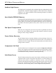
ECU-MAXX OPERATIONS MANUAL Ambient Light Sensor The display panel is equipped with an ambient light sensor (photodiode) which automatically controls the display brightness. This feature allows maximum visibility in very bright conditions while maintaining adequate but subdued brightness in the dark. Non-Volatile EEPROM Memory Operating and programmed parameters are entered into nonvolatile memory.
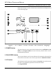
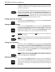
ECU-MAXX OPERATIONS MANUAL OPERATOR CONTROLS & DISPLAY PANEL Please refer to Figure 1, below, for the location of the buttons and displays listed on the following pages: 1. POWER button The power button is used to switch the ECU-Maxx between Off Mode and On Mode, enter Program Mode and reset the Factory Default Values for the programmable parameters. 2.
ECU-MAXX OPERATIONS MANUAL 4. DOWN button The Down button is used to decrease the temperature set point value, and to decrease the value of programmable parameters when the ECU-Maxx is in Program Mode. 5. MODE button The Mode button is used to switch between the various modes of operation of the ECU-Maxx. The modes are AUTO, HEAT, COOL and MOISTURE CONTROL. This button is also used to scroll up through the programmable features in Program Mode. 6.
ECU-MAXX OPERATIONS MANUAL 15. INSIDE AIR TEMPERATURE light When the Inside Air Temperature indicator LED is lit, the 3-digit display will provide a readout of the inside air temperature as detected by the inside air sensor (located on the face plate unless the alternate air sensor is installed). 16. OUTSIDE AIR TEMPERATURE light When the Outside Air Temperature indicator LED is lit, the 3-digit display will provide a readout of the outside air temperature as detected by the outside air sensor. 17.
ECU-MAXX OPERATIONS MANUAL Temperature Hysteresis Temperature is automatically maintained within the programmed temperature range of the set point. For example, the factory default value for the temperature hysteresis is 2º: When the temperature requirement has been satisfied, a 2º shift is required to establish demand. A 4º shift is required to change from one mode to the other. Once the required heating or cooling mode has been established, the hysteresis remains 2º.
ECU-MAXX OPERATIONS MANUAL Repeatedly press the Mode button until the Cool Mode indicator LED is on, and cooling will be supplied when required. Selecting Heat Only Mode Repeatedly press the Mode button until the Heat Mode indicator LED is on, and heating will be supplied when required. Note: If the water temperature is below the low water limit, the valve and compressor will turn off and heat will be supplied by the optional CAL rod heater, if installed.
ECU-MAXX OPERATIONS MANUAL temperature differential. This speed reduction does not take place until the temperature differential between the ambient temperature and the set point is less than 6º (six degrees). The maximum temperature differential may be increased from 6º to 12º by changing the programmable parameter Automatic Fan Speed Spread. The increase in the spread from 6º to 12º results in one fan speed reduction for every 2º decrease in temperature.
ECU-MAXX OPERATIONS MANUAL 1. AC Line Voltage (Voltmeter) (code "AC") 2. AC Amperage (Ammeter) (code "cur") 3. Water Sensor (code "H2O") 4. Total Compressor Run Time (in hours) (code "crt") 5. Freon Low Pressure (code "L-P") 6. Freon High Pressure (code "H-P") 7. AC Line Frequency (50 or 60 Hz) (code "FrE") Exit View Mode by pressing the Temp Select Button. This will return the unit to normal operation. The ECU-Maxx will exit View Mode automatically if no buttons are pressed for 1 (one) minute.
ECU-MAXX OPERATIONS MANUAL Using Program Mode The program parameters are displayed by pressing the Mode button or the Temp select button. Program parameters are designated by "P-nn" in the display, where "nn" is a number from 1 to 34. Pressing the Mode button repeatedly will cause the display to scroll up through all the program parameters. Pressing the Temp Select button will cause the display to scroll down through all the program parameters.
ECU-MAXX OPERATIONS MANUAL P-2: Moisture Control Mode High Temp Set Point This function sets the minimum cooling temperature that will be maintained in Moisture Control Mode. The range for this value is between 95º F and 77º F. The room temperature where the ECU-Maxx display panel is located (unless a remote air Temp. Sensor has been installed) will not be allowed to exceed the temperature selected by this set point. Use the Up and Down buttons to select the temperature.
ECU-MAXX OPERATIONS MANUAL P-8: High Fan Speed Limit The upper limit of the fan speed can be reduced to tailor the fan output for various motors. The range of values for the high fan speed are 50 through 80 in arbitrary units. The high fan limit is not permitted above 220 VAC to prevent excessive fan noise. Use the Up and Down buttons to select the fan speed preset. The factory default setting of this function is 70.
ECU-MAXX OPERATIONS MANUAL P13: High Water Limit The high water limit defines the availability of cooling water for the condenser coil. The water pump and compressor are not allowed to operate above the high water limit. High water temperatures at the condenser inlet usually indicate a lack of cooling water. Temperatures at or above the high water limit are indicated by alternately flashing "H-I" and then "H2O" in the display. Fail-safe protection levels apply to the high water limit.
ECU-MAXX OPERATIONS MANUAL P18: High Pressure Freon Switch Disable This option has been provided to disable High Pressure Faults in heating mode only, since high head pressure can be an acceptable occurrence while heating. This function is only valid if P16 is enabled. P19: Low Pressure Freon Switch Hold-Off Delay Low Freon pressure conditions can occur during normal operation. To prevent erroneous LP faults from occurring a hold-off delay is provided.
ECU-MAXX OPERATIONS MANUAL ON - A continued low line voltage condition for 5 minutes will cause the compressor to turn off while the fault code "LO-AC" flashes with the line voltage in the display. After 4 successive failures the system requires a manual restart.
ECU-MAXX OPERATIONS MANUAL P27: Soft Start Ramp Delay The compressor soft start feature is a factory-installed option on the ECU-Maxx, developed to reduce the electrical loading placed on the system when the compressor starts up. If soft start has been installed on your system, the Soft Start Ramp Delay Option will adjust the ramp time from 0 to 5 seconds (see system timing diagram in the System Control algorithm section). The factory default setting is 2 seconds.
ECU-MAXX OPERATIONS MANUAL P30: Station ID Number Used to identify the control's placement when connected with the Lan-Maxx network option. P31: Winterization System Option This option is used when there is no sea water available. With this option ON, the sea water pump is disabled and Heat is provided by an Electric Heater ONLY. Provides electric heat in colder climates or when the boat is out of the water. P32: No Reverse Cycle Heating This option is for cooling only units without reversing valves.
ECU-MAXX OPERATIONS MANUAL P ro g N um P rogra mmable P arame te r PROGRAM TABLE Fa cto ry D e fa ult S e tting s Pe rmitte d Va lue s o r R a ng e s L e ve l 1 1 ,2 o r 3 P-1 M o ist C ntrl M o d e D e humid ific a tio n Le ve l P-2 M o ist C ntrl M o d e H igh Te mp S e t P o int 85º F 77 ºF to 9 5º F / 2 3° C to 35° C P-3 M o ist C ntrl M o d e L o w Te mp S e t P o int 55º F 5 0 º F to 6 9 ºF P-4 C yc le P ump W ith C o mp re sso r O ff = C o ntinuo us O n = P ump C yc le s W ith C o mp
ECU-MAXX OPERATIONS MANUAL THEORY OF OPERATION ECU-Maxx System Timing The following discussion explains the steps the ECU-Maxx control takes at the beginning of a heating or cooling cycle. There are two different start-up protocols: timed start and soft start. Soft start has been developed to reduce the starting load placed on the electrical system by the compressor. It is an optional feature and must be installed by the factory. Timed start does not provide the load limiting features of soft start.
ECU-MAXX OPERATIONS MANUAL ECU-Maxx VER:10a 12/1/97 SYSTEM TIMING DIAGRAM PAGE 22
ECU-MAXX OPERATIONS MANUAL SYSTEM INPUTS AND OUTPUTS Internal Sensor Inputs The ECU-Maxx has four internal sensors: 1. 2. 3. 4. Control Panel Air Temperature Sensor Control Panel Ambient Light Sensor AC Line Voltage System Amperage External Sensor Inputs The standard ECU-Maxx has inputs for three external sensors. Please refer to Figure 3 for a graphic representation of where these inputs are. 1. Alternate Air / Outside Air Temperature Sensor 2. High Freon Pressure Input (Optional) 3.
ECU-MAXX OPERATIONS MANUAL ECU-Maxx VER:10a 12/1/97 ECU-MAXX INPUTS AND OUTPUTS PAGE 24
Action Taken by ECU-Maxx Air Sensor Fault AIR Complete shutdown until the fault is cleared. Water Sensor Fault H2O High Pressure Fault Level 1 Leve YES YE Shutdown of water pump until the fault is cleared. NO YE H-P Shutdown of compressor until the fault is cleared. NO YE Low Pressure Fault L-P Shutdown of compressor until the fault is cleared. NO YE Sustained Low Line Voltage Fault Shutdown OFF L-O A-C Unit will continue to operate.
ECU-MAXX OPERATIONS MANUAL FAULT HANDLING & FAIL-SAFE MODES Fail-Safe There are three levels of fail-safe protection. Level 1 is the lowest. In this level, the sensors are not monitored for faults. In the two other levels, the sensor is monitored for faults. In level 2, if a fault is detected, the fault code is displayed, but no other action is taken. In level 3, the fault is displayed and the compressor is shut down.
ECU-MAXX OPERATIONS MANUAL 416 OPTION BOARD An Optional Accessory Board may be ordered for the ECU-Maxx [Part Number: 416-X0A].
ECU-MAXX OPERATIONS MANUAL ECU-Maxx VER:10a 12/1/97 TYPICAL APPLICATION PAGE 28
ECU-MAXX OPERATIONS MANUAL SPECIFICATIONS S E T P OIN T R AN GE D IS P L AY T EM P R AN GE L OW V OLTAGE D E T E C TION P ro gra m m ab le 60 ° F to 85 ° F ZE R O (0) to 1 60 ° F 11 5 V OLT U N IT S 2 20 V OLT U N IT S 85 VAC 1 85 VAC S E N S OR AC C U R AC Y ± 2 ° F at 77 ° F FU S IN G E L E C TR ON IC V OLTAGE 11 0 o r 2 20 VAC at 50 o r 60 H z FAN OU TP U T 25 AMP S a t 2 20 VAC VALV E 25 AMP S a t 2 20 VAC P U MP 25 AMP S a t 2 20 VAC C OMP R E S S OR 40 AMP S a t 2 20 VAC C AL R OD H
ECU-MAXX OPERATIONS MANUAL FACTORY PROGRAMMING OPTIONS F-1 THROUGH F-8 Enter the factory program mode by first entering the programming mode then pressing the power and fan buttons simultaneously. Use the mode button to move forward and the Temp select button to scroll back through the factory program items. Once in the factory mode the following program changes can be made: F-1: Voltage Calibration The systems volt meter can be adjusted plus or minus 10 volts AC. Use this item to calibrate the voltmeter.
ECU-MAXX OPERATIONS MANUAL REVISION HISTORY Revision: 08 First revision from Wendy's original manual. Update from original ECU-Maxx to Software versions 2.7 through 3.5. Corrected wiring diagrams, program tables and general contents. Revision: 09 Changed page 28 typical application to reflect new PC board. Changed P16 and P17 descriptions to include default settings to ON. Boards are supplied with jumpers on the high and low Freon switches and factory defaults allow switches ON.