Software for infrared camera thermoIMAGER 160 Operators manual thermoIMAGER TIM Connect
Content Content........................................................................................ 2 Welcome! .................................................................................... 4 Warranty ...................................................................................... 5 1. Getting Started ................................................................. 6 1.1. Software Installation................................................6 1.2. Choice of Camera............................
.4.7. Location and Filename Templates of Triggered Recordings ......................................................45 3.4.8. Display of Snapshots in a Separate Window .46 3.4.9. Saving Images or Screenshots to Clipboard .46 4. Data Processing............................................................. 47 4.1. Measure Areas ......................................................47 4.2. Temperature Profile ..............................................52 4.3. Temperature Time Diagram.......................
Welcome! Thank you for choosing the thermoIMAGER TIM Connect software! The thermoIMAGER TIM calculates the surface temperature based on the emitted infrared energy of objects [► Basics of Infrared Thermometry]. The two-dimensional detector (FPA - focal plain array) allows a measurement of 160 x 120 or 382 x 288 pixels and will be shown as thermographic image using standardized palettes.
Warranty All products manufactured by MICRO-EPSILON Messtechnik GmbH & Co KG are warranted against defective materials and workmanship for a period of one (1) year from the delivery date of the original purchase, provided such products have been under normal storage, use and service, and in accordance with MICRO-EPSILON Messtechnik GmbH & Co KG instruction. This warranty expires in case of inappropriate use of all delivered components.
1. Getting Started 1.1. Software Installation Please install at first the software TIM Connect from the CD. The CD contains the software application, the specific calibration data of the imager as well as some sample files. These data will be installed automatically. Note Before installing the new software please uninstall earlier versions of the TIM Connect. If you want to uninstall the software from your system please use the uninstall icon in the start menu.
1.2. Choice of Camera In case you are using more than one TIM simultaneously (e.g. via USB hub) please select the required TIM from the list in the Devices menu. 1.3. Choice of Language In the Tools and Language menu you can choose from a variety of available languages. Note In case your language is not provided you will find a translation tool on the software CD delivered with the camera.
1.4.
1 IR image from the camera 2 Temperature profile: Shows the temperatures along max. 2 lines at any size and position in the image. 3 Reference bar: Shows the scaling of temperature within the color palette. 4 Temperature of measure area: Analyses the temperature according to the selected shape, e.g. average temperature of the rectangle. The value is shown inside the IR image and the control displays.
1.5. Menu and Toolbar (Icons) 1.5.1. Menu Using the menu you can adjust all software settings.
1.5.2. Toolbar (Icons) The most important features of the software can be activated directly via the toolbar. You can redesign the toolbar according to your preferences (see section 2.2.2).
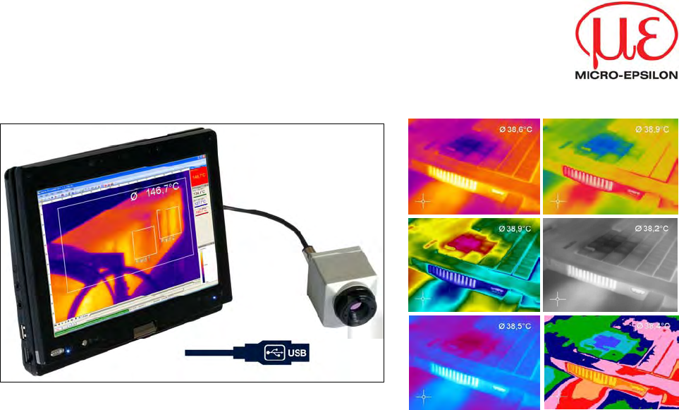
2. Software Configuration 2.1. General Settings You can activate all here mentioned features in the Tools, Configuration and Genera menu (except for color palettes). 2.1.1. Color Palettes In the Tools, Configuration, Measuring colors and Standard palette menu you can choose from a list of color palettes to achieve ideal displaying of the infrared image and the included temperature information. You can also adjust the color palette via the Icon on the toolbar or the menu View and Shift palette.
Palette Iron Palette Rainbow Palette Blue Hi Palette Rainbow Hi Palette Rainbow Medical Palette Gray (Black = Cold) thermoIMAGER TIM 13
2.1.2. Temperature Unit When setting the Temperature unit you can choose between Celsius (°C) and Fahrenheit (°F). 2.1.3. Temperature Range of Reference Bar Via Min. and Max. settings you can allocate colors to temperature values within the reference bar . These are the following options: Manual The upper and the lower border can be determined individually. The software continuously defines the upper and the lower border based on the hottest and coldest pixel in the image.
2.1.4. Displayed Frame Rate The option Reduce displayed frames defines what frame rate is used to display the image. Typically, the specification is in Hertz (Hz, images per second). The maximum frame rate of the imager is 120 Hz. The camera supplies the software all images all the time. Reducing frame rate means that some images will not be considered. The specified algorithm defines which images will be displayed or not: Off The displayed frame rate will be 120 Hz.
Note A reduced frame rate means a less loaded computer in terms of data processing. Therefore, please adjust the displayed frame rate according to your application as well as to the performance of your computer. 2.1.5. Change of Title Bar The Application title bar option enables the individual setting of title bar. The setting Default displays the standard software name „Optris TIM Connect“. Using the setting User defined you can specify an individual name.
2.2. Software Layout 2.2.1. Displayed Windows You can individually choose the displayed windows and easily change their positions within the desktop area (drag & drop). To add windows please use the menu item View and Windows. On the one hand a window can be positioned separately on the screen. On the other hand a window can be set at a fixed position in the software. The location can be determined using the positioning field (mouse over the arrows „above“, „below“, „right“, „left“).
2.2.2. View Bars For individual display of software you can show or hide single bars in the software window. There is the possibility to Show all bars or Hide all bars by one click. Note All icons shown on the toolbar can be individually selected via the option Customize tool bar… (Please see also 1.5.2). 2.2.3. Information Within Image Using the menu View and Image Information you can decide, which information you would like to see inside the infrared image window.
The menu item Use contrast color can be used for highlighting particular information within the IR image. Display of thermal image without and with contrast colors 2.2.4. Temperatures in Digital Displays The menu option View and Digital display group temperatures allows the user to define which temperature control displays will be shown in the application window Temperatures (see section 2.2.1). The shown pre-defined values can also be displayed in the temperature time diagram (see section 4.3).
2.2.5. Layout Management In the menu item View and Layouts you can manage pre-designed or your own image layouts. If you want to use an alternative layout you must activate it under Load layout. You can save your own layouts with user-defined names. Note Before you click Save layout you must add new layout name into the field provided.
2.2.6. Assign / Remove Layouts In the menu item Edit and Assign layout to current file you can save files with a new layout setting. Using Remove layout from current file it is possible to configure a file in a way that it has no associated layout pattern. When you play it again the layout of the previously played file will be used. Note To confirm the changes as explained above you must always save the file. Please use the menu File and Save or the Icon on the toolbar. 2.2.7.
2.3. Arranging of Thermal Image The thermal image within the main window of the software can be displayed in various ways using the menu Tools, Configuration and IR Image arranging. 2.3.1. Mirroring of Displayed Image Sometimes, depending on the fitting position of the TIM, it is useful to Mirror the camera image horizontally or vertically. Either the image will be adjusted by the menu mentioned above or under Tools and Mirror. 2.3.2.
Rotation and zooming of a defined measure area.
2.4. Imager Configuration 2.4.1. Calibration Files The menu Tools, Extended and Reimport calibration files enables to boot the calibration data for the currently connected TIM. 2.4.2. Correction of Camera Calibration Due to the thermal drift of bolometers all measuring IR cameras need an offset correction every few minutes. This correction is done by a motor driven motion of a blackened metal piece (so called flag) in the front of the image sensor.
Using the option Flag operation while recording and Use flag the correction is activated even if the camera is recording. If Avoid flag is chosen the camera will not be corrected while recording. The option Use flag while skipped frames is suitable at slow data capturing (3 Hz or less) as the correction will take place automatically between two recorded images (correction time app. 250 ms). Note The manual or automatic flag functionality is not available if the flag is externally controlled, e.g.
Note In case that the emissivity and / or the ambient temperature values are controlled through the Process Interface (PIF) the here defined values will be ignored (please also see 2.5). The display of actual values will be shown in the status bar. 2.4.4. Reference Temperature The detector of the thermoIMAGER has a thermal drift over the time and must be corrected by self referencing.
There are several Fitting modes to adjust the thermal image: Auto The software is choosing the best way of correcting the image (offset or gain). Offset This kind of correction is recommended if there are big temperature differences between the reference temperature value and the thermal image. Gain This kind of correction is recommended if there are small temperature differences between the reference temperature value and the thermal image.
2.4.5. Changing the Optics Using the menu Tools, Configuration and Device the Optics depending on the camera configuration must be chosen. As a standard the camera can be delivered with a 6 °, 23 ° or 48 ° lens. If the camera is ordered with several additional lenses the currently used optics must be chosen in this menu. The option Radial Distortion Correction enables the alteration of the original shape of the image delivered by the TIM (barrel distortion correction).
2.5. Imager Interfaces 2.5.1. General The TIM is equipped with a process interface (cable with integrated electronics and terminal block), which can be programmed via the software as an Analog Input (AI) and Digital Input (DI) in order to control the camera or as an Analog Output (AO) in order to control the process. The signal level is always 0 -10 V.
2.5.2. Process Interface (PIF) Using Tools, Configuration and Device PIF menu you can activate the Process interface (AI) as an input. The emissivity, ambient temperature value and reference temperature can be scaled between 0 -10 V. For the other options you need to define a voltage value as a Threshold [V] – the option is activated if the value is above this threshold. If the box is tagged the threshold value below will activate the action.
The process interface has an integrated failsafe mode. This allows to control conditions like interruption of cables, shut-down of the software etc. and to give out these conditions as an alarm.
2.6. Imager Interfaces 2.6.1. Interprocess Communication (IPC) Tools, Configuration, External Communication and Interprocess Communication (IPC) enables you to embed colors, temperatures or ADU values into other applications via Dynamic Link Library (DLL). 2.6.2. Comport You can activate the feature in the Tools, Configuration, External Communication and Comport menu. If selected the data values sent out by the camera can be transmitted via specified Port. The baud rate can be changed accordingly.
2.7. Start Options 2.7.1. Overview of Start Options TIM Connect software can be started with additional starting parameters using the command line. Please change the linkage in the software settings via the launch icon on the desktop. Behind the command line please add a space character and the required command parameter, e.g. "C:\Program\MICRO-EPSILON GmbH u Co KG\TIM Connect\Imager.
Note Using the parameter Invisible the software can only be closed via the Task Manager and Processes. 2.7.2. Start of Multiple Software / Imager Instances In case you are using more than one TIM simultaneously each imager can be linked to one software instance. In order to setup a further software instance please follow the steps below: 1.) Duplicate the software icon at the desktop 2.) Change the name of the new software icon at the desktop, e.g. „Imager1“ 3.
3. Data Capturing 3.1. Open Files Via the menu File and Open or the Icon on the toolbar you can open all files which can be processed by the software. Note Via the menu File and Reopen you can easily reopen captured files if the option in 3.4.6 is activated. 3.2. Replay of Files 3.2.1. Control Panel In order to replay a video sequence you can use different options in the File menu or at the control panel.
3.2.2. Replay Options Via the menu Tools, Configuration, Playing and Playing options you can modify the play rate of recorded video sequences. This feature ensures that you can replay a video of a fast process in slow motion in order to analyze it in more details. Additionally, you can define to replay a recorded video in a loop (Infinitive loop playing) or to play selection only. To define a selection the position marks on the time bar needs to be set.
3.3. Editing Video Sequences The selected video can be edited by using Trim to selection and Cut out selection options in the Edit menu. A time bar tool is shown on the bottom of the image. Set the position marks on the time bar to select the beginning and end of the video sequence you want to be edited. 1 The not selected video sequence parts (bright grey) will be deleted by choosing Trim to selection option. The selected video sequence (dark grey) will remain.
3.4. Saving Files 3.4.1. Setting the Recording Frame Rate The camera’s maximum frame rate of 120 Hz can be reduced. Using Tools, Configuration, Recording and Recording frame rate the speed of the data capturing can be set. Typically, the specification is in Hertz (Hz, images per second). The software gets the full frame rate from camera. That is why you need to define what to do with the images which are left if choosing a reduced frame rate.
compose a new averaged image. Recording frame rate referring to 1 pixel 3.4.2. Setting the Recording Modes If desired the Recording time limit sets fixed recording time in seconds. After reaching the time limit the software stops the recording. If activating Radiometric recording the temperature value of each pixel as well as information on defined measure areas are recorded. Videos containing these data (RAVI files) allow users to do a detailed post-analysis anytime later.
Note If Radiometric Recording is not activated the images will be saved as standard AVI file only containing color information. A later conversion of a RAVI file into an AVI file and vice versa is not possible. Choosing the option Save after recording is stopped the images will be saved without further notice. If the option Play after recording is stopped is activated the saved images will be played automatically in the main window. Note The status of recording is displayed at the bottom notice bar.
3.4.4. Saving Radiometric Video Sequences or AVI Files Video sequences can both be saved as a radiometric file (RAVI) or as a non-radiometric file (AVI). RAVI files contain all temperature as well as measure area information. Note If Radiometric Recording (please see section 3.4.2) is not activated the images will be saved as standard AVI file only containing color information. A later conversion of a RAVI file into an AVI file and vice versa is not possible.
3.4.5. Saving Image Data as Radiometric Snapshot or Text File Snapshots are single, radiometric images based on a video sequence, this means they are contain all temperature as well as measure area information. Thus the images can always be analyzed in detail later on. Snapshots can be captured via the menu File and Snapshot or via the Icon on the toolbar.
In the Tools, Configuration and Trig. Recording / Snapshots menu you define the File type for triggered snapshots. The option Max. triggered snapshots in history window sets the number of displayed snapshots in the separate window Snapshot history (please see section 2.2.1). If Ignore last snapshot for history is activated only the latest snapshot will be displayed in the Snapshot history window if a new snapshot is captured. There are the following options to save image data: TIFF (*.
Analysis of thermal image in Excel via *.
3.4.6. Saving Text File of the Temperature / Time Diagram Via the menu File and Saving temp/time diagram data the data of diagram can be saved in a text file (*.dat) for further analysis. 3.4.7. Location and Filename Templates of Triggered Recordings In the Tools, Configuration and Trig. Recording / Snapshots menu you can define a Prefix for filename. The software is using this prefix if saving a sequence or snapshot. The path defines the storage location of all files and can be changed here.
3.4.8. Display of Snapshots in a Separate Window In the menu View, Windows and Snapshot history you can activate a window in order to display all triggered snapshots (please also see section 2.2.1). 3.4.9. Saving Images or Screenshots to Clipboard Using the File and Copy to clipboard menu or the Icon on the toolbar the image of the main window can be copied to the clipboard in order to paste it into different programs such as MS Word.
4. Data Processing 4.1. Measure Areas 4.1.1. General Settings Measure areas for temperature analysis can be defined, edited and deleted using the menu Tools, Configuration and Measure areas. Using New / Delete buttons you can create a new measure area (measure point / rectangle) or delete existing measure areas. Press Up / Down to position individual measure areas within the list. 1 measure area from the list can be appointed as the Main measure area.
Available measure areas (modes) are: Position (X, Y) User defined rectangle Measure point (1x1) Measure point (3x3) Measure point (5x5) Any measure area can be renamed individually in the Name field. The Mode option allows you to define the type of area as measure point or rectangle. The temperature of the main measure area can be displayed in the main window. Available value types are Minimum, Mean value or Maximum. It is also possible to use the Icon on the toolbar.
In the Position section the exact position of the measure area within the main window can be defined. If desired the area can represent a Hot spot (spot or area with highest mean temperature in the image) or a Cold spot (spot or area with lowest mean temperature in the image). Using Center you will be moving the measure area into the middle of the main window, using Standard size the rectangle will be set in a predefined size.
4.1.2. Excluding Hot and Cold Spot Areas Using the menu Tools, Configuration, Measure areas and Edit excluded areas of hotspots/coldspots you can exclude existing or potential hot or cold spots from data analysis. Within the user defined areas of the image the spots will not be taken into consideration. A new area can be edited via the button Add a new spot exclude area or deleted via the button Remove this spot exclude area.
4.1.3. Individual Emissivity Values of Measure Areas In case of measuring several materials different emissivity values can be set within the image. Using the menu Tools, Configuration, Measure areas and Emissivity the individual emissivity values can be defined. The display of the changing temperature values within the measure areas will remain linked to the colors of the reference bar.
4.2. Temperature Profile Up to 2 temperature profiles which graphically reproduce the temperature development can be generated. The profiles are labeled as Profile 1 and Profile 2. The position and size of the profiles can be defined via the coordinates Begin (P1) and End (P2). Select Show in image if you want the profiles to be displayed in the infrared image in the main window. Alternatively, this setting can be made by choosing the menu View and Image information (please see section 2.2.3).
The temperature profiles can be displayed in additional windows (please see section 2.2.1). Using the options Show in horizontal diagram and Show in vertical diagram the profiles can be assigned to the horizontal and / or vertical diagram window. The option Range allows you to choose between automatic or manual adjustment of the temperature scaling within the diagram. There are two possibilities of displaying the profile Curve in the profile diagram.
Use Bind measure areas to profile to assign various measure areas to a temperature profile. If the position of the profile is changed all the measure areas will also be moved. The respective profile can be chosen via the option Assign measure areas to. Prefix for measure area name enables the individual labeling of measure areas. The measure area type can be defined under the Mode options.
4.3. Temperature Time Diagram 4.3.1. General Settings In the Tools, Configuration and Temp/Time Diagram menu you can display the temperature over time for each configured measure area as well as for predefined values (please also see 2.2.4). The Show options define if a certain temperature value is displayed or not. If the Graph is shown you can decide whether to illustrate the Name or not. If activating the option Auto range the respective graph is influencing the auto ranging of the diagram.
In the diagram measuring settings you can define the maximum of data (Max. data count) which is displayed in the diagram. 1.000 x 10.000 results in 10.000.000 (ten millions) data values; the needed Memory will be calculated automatically. Using the option Auto (device framerate) the Recording time is calculated based on the frame rate of the camera (please also see 3.4.1). Independent from the frame rate of the camera you can individually set the number of data.
Control elements of the time axis 1 Scroll bar to choose time segment. 2 Zoom (increase) into the diagram. The temperature axis will remain. 3 Zoom (decrease) into the diagram. The temperature axis will remain. 4 Whole range: Display of whole time axis, e.g. of a stored video sequence. 5 H: Hold/ C: Continue: Any activation of the H control element will stop the further actualization of the measurement graph. The measurement itself continues in the background.
10 Zoom (decrease) into the diagram. The time axis will remain. 11 Whole range: Display of whole temperature range which is set in the camera. 4.4. Histogram The Histogram feature shows the distribution of pixel intensity values within a thermal image. The X-axis of the histogram represents the pixel intensity and the Y-axis represents the percent of color count for each pixel intensity value. In the Tools, Configuration and Histogram menu you can adjust various settings.
Further options are: Display current temperature If activated the red line will show the current temperature at the mouse in the graph. Display mean and sigma value: Average temperature and statistical deviation 1σ (1 Sigma) will be displayed. Use palette colors You can choose between colored or black/white presentation. Class size Number of values measured which should be affiliated to one class for common colored display.
4.5. Extended Measuring Colors The Tools, Configuration, Measuring colors and Extended Measuring colors menus offer you the possibility to change the pixel color within the image if the temperature Range reaches predefined low and/or high temperature values. Doing this you can visualize temperature gradients. Furthermore, the display of isotherms (colored display of temperature group) is possible. Via the Threshold definition you can set two temperature values.
4.6. Image Subtraction Once you have activated the feature by using Image subtraction in the Devices menu or via the Icon on the toolbar, an image is saved in the background and a temperature difference is calculated and displayed for all the following images. Image subtraction is not activated. The current averaged temperature of the measure area is displayed in the right top corner.
4.7. Relative Extreme Values Within the Tools, Configuration and Extended measurement menu it is possible to exclude pixel within the thermal image from data analysis. Using Ignore pixels with temperatures a temperature can be set as lowest (below) or highest (above) value. In case of analyzing an image using measure areas (For measure areas) the calculation of e.g. the mean value is not taking values below or above the set limits into account.
4.8. Alarms In the Tools, Configuration and Alarms menu you can define an alarm for each configured measure area as well as for the predefined values (please also see 2.2.4). The alarm values can be displayed as figures in the digital display or in a graphical way as a bar. For the latter you need to activate the option Show Graph Bar. Regarding the bar you can define via Display ranges the Min. and Max. value (temperature borders).
If a temperature value shall be used as alarm you need to tag the Alarm option. If active, the alarm can also be put out via the Process Interface (PIF) using the Alarm to PIF option. Note If activating the alarm a red alarm button on the toolbar appears. You can deactivate the visual and acoustic alarm by clicking on the alarm button. The alarm will stay deactivate until the alarm value is reached again. In the Alarm configuration window you can set an audible alarm.
Furthermore, a recording can be stopped via Abort recording if alarm condition drops out. If this option is not chosen the recording will be finished based on the time in the duration box. With the Snapshot on alarm option you can set a Delay [sec] time before an alarm will trigger the storage of an image. 4.9. 3D Display of Thermal Image Thermal images can be displayed in real time as 3 dimensional images. The 3D chart is displayed in a separate window.
5. Visual Camera (TIM200 only) 5.1. Enabling the Visual Camera The TIM200 thermal imager features a visual camera. With the help of BI-SPECTRAL technology, the visual image (VIS) can be combined with a thermal image (IR). Both can be finally captured time synchronously. The visual camera can be enabled in the Tools, Configuration and General menu via the option „Use visible camera“. The menu Tools, Configuration and Device displays the Video formats depending on the current imager’s configuration.
Note The rectangle within the visual image shows the area covered by the thermal image. In order to cover a big area the wide-angle lens is used, to cover a smaller area the telephoto lens. In the View, Image Information and IR rectangle menu it is possible to hide the displayed rectangle. 5.3. Cross-fading Modus 5.3.1. General The cross-fading modus is used in order to highlight critical temperatures at the point of measurement. In this modus the thermal image is faded into the visual image.
5.3.2. Transparency of Thermal Image The thermal image can smoothly be faded into the visual image (0 … 100 %). To set the transparency value please use the Tools, Configuration, Measuring colors menu and Standard palette / Transparency [%]. 0% 50 % 100 % The thermal image is fully faded into the visual image. The thermal image is partly (50 %) faded into the visual image. Using this setting the ideal relation of both images can be defined (please see section 5.3.3).
5.3.3. Moving the Thermal within the Visual Image Due to the different optical axis of visual and thermal channel the relation of both images needs to be optimized. If moving the cursor to the edges of the rectangle‘s frame the grippers can be used to adjust the size of thermal image or to move the image completely (hold STRG synchronously).
5.3.4. Cross-fading of Defined Temperatures The cross-fading modus can be combined with the Extended Measuring colors option (e.g. for isothermal display of temperatures, also see section 4.5). To set the level of fading this option into the visual image use the Tools, Configuration, Measuring colors and Extended Measuring colors / Transparency [%] menus: 0% 50 % The set option is fully faded into the visual image. The set option is partly (50 %) faded into the visual image.
6. Linescanner Mode 6.1. General Information The TIM Connect software comes with a linescanner function. The linescanner mode is generally used for continuous processes with moving objects under test, such as measurement of rotary kilns or measurement of great lots at conveyor belts (batch process).
6.2. Basic Settings 6.2.1. Linescanner Configuration Menu All the settings related to the linescanner mode can be done through the Linescanner configuration menu. You will find the menu under Tools, Linescanner mode and Linescanner settings or as an Icon on the tool bar. 6.2.2. Choosing the Layout Before you configure the Linescanner mode a suitable layout (e. g. alignment of application windows) should be chosen or created. You will find more details in chapter 2.2. 6.2.3.
6.2.4. Activating the Linescanner In order to configure the Linescanner it is necessary to activate the Linescanner mode under Tools, Linescanner mode and Enable Linescanner or using the Icon on the tool bar. Note There are two view options available under Linescanner mode. Linescanner sighting view is showing the position of the line and self-trigger area within the infrared image taken by the camera. Linescanner view delivers the resulting infrared image based on temperature readings for selected lines.
from 4 different direction options provided (see below image X scan top-down (rows) and scan bottom-up (rows) and image Y scan left to right (columns) and scan right to left (columns). 6.2.6. Layout Configuration of the Sighting View Mode The displayed linescanner sighting views visualize the 4 possibilites how to capture and finally represent multiple lines in the linescanner view You can make further modifications to the Sighting view mode using Extended menu.
6.3. Data Evaluation of the Scanned Line 6.3.1. Linescannner View In the linescanner view readings will displayed as an infrared image. To activate this view mode you can use the icon provided. Note This icon enables to switch between Linescanner sighting view and Linescanner view. Presentation of the scanned lines can be further defined in Linescanner configuration application window (see 6.2.1) under Presentation. Direction option defines in which direction the scanned lines will be displayed.
automatically using an external trigger input (see 6.3.2). In Resulting linerate (Hz) field calculated frame rate of each line will appear automatically. Keep aspect ratio option will adjust width of each line so that all lines will appear within the infrared image. 6.3.2. Triggered Display of Lines Triggering signal can be used to control how the scanned lines will be arranged within the Linescanner view. In the General menu under Linescanner configuration (see 6.2.1) there are two options provided.
If activated Avoid re-triggering during scan will not allow to run a new linescan cycle while a previous cycle trigger by recent signal is not finished. Note For external triggering it is necessary to do modifications of the standard configuration on the Process Interface (PIF). You will find more details in the chapter 2.5. Using the Self triggered option it is possible to use a triggering signal provided by software to control arranging of the scanned lines.
Within the trigger area Trigger thresholds temperatures can be set to trigger the linescan cycle. Holdoff time [s] determines time frame within new signal should be neglected (e. g. if a signal from the heat source in the background is triggered). Under Flag operation and Avoid during scan can be set that refreshing of flag will not be executed during the linescan (see also 2.4.2). Force after scan will execute the flag once given number of scanned lines is provided. 6.3.3.
7. Further Information 7.1. Activating Software Messages At some point a warning message will appear when performing an action that would cause changes to software settings. To prevent unintended changes you can activate or deactivate these messages by using Tools, Extended and Options. Note If a message appears you can disable the window by choosing „Never ask me again“. Using the menu Options you can activate the appearance of the window again.
Important options are: Warning if unsaved data exists Ask for keeping measuring objects… Ask for stopping triggered recordings… thermoIMAGER TIM If activated a reminder will appear to warn you on unsaved data or setups before shutting down the software You can choose to maintain already created measure areas and temperature profile lines, if you rotate or zoom the displayed image.
7.2. System Requirements Minimum system requirements: Windows XP (Service Pack 3) USB 2.0-interface Hard disc with at least 30 MByte free space At least 256 MByte RAM CD-ROM-drive Recommended system requirements: Windows 7 At least 2 GB hard disk storage for IR videos At least 2 GB RAM 7.3. About Software In the Help and About submenu you will find the version name of TIM Connect software you are currently running.
7.4.
Alt+P Ctrl+Alt+P Alt+Enter Next palette Previous palette Full screen Alt+S Image subtraction Alt+H Horizontal mirror Alt+V Vertical mirror Ctrl+Alt+S Image subtraction from file Ctrl+L Line scanner sighting view Ctrl+Alt+L Enable line scanner thermoIMAGER TIM 83
MICRO-EPSILON MESSTECHNIK GmbH & Co. KG Königbacher Str. 15 · 94496 Ortenburg / Germany Tel. +49 (0) 8542 / 168-0 · Fax +49 (0) 8542 / 168-90 info@micro-epsilon.de · www.micro-epsilon.