
Specifications


Table Of Contents
- Content
- Welcome!
- Warranty
- 1. Getting Started
- 2. Software Configuration
- 3. Data Capturing
- 3.1. Open Files
- 3.2. Replay of Files
- 3.3. Editing Video Sequences
- 3.4. Saving Files
- 3.4.1. Setting the Recording Frame Rate
- 3.4.2. Setting the Recording Modes
- 3.4.3. Temporary Recording File
- 3.4.4. Saving Radiometric Video Sequences or AVI Files
- 3.4.5. Saving Image Data as Radiometric Snapshot or Text File
- 3.4.6. Saving Text File of the Temperature / Time Diagram
- 3.4.7. Location and Filename Templates of Triggered Recordings
- 3.4.8. Display of Snapshots in a Separate Window
- 3.4.9. Saving Images or Screenshots to Clipboard
- 4. Data Processing
- 5. Visual Camera (TIM200 only)
- Linescanner Mode
- 7. Further Information
thermoIMAGER TIM 29
2.5. Imager Interfaces
2.5.1. General
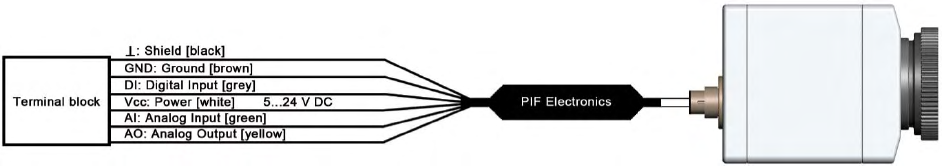
The TIM is equipped with a process interface (cable with integrated electronics and terminal block), which can
be programmed via the software as an Analog Input (AI) and Digital Input (DI) in order to control the camera or
as an Analog Output (AO) in order to control the process. The signal level is always 0 -10 V. The process
interface can be activated choosing the following options:
Analog Input (AI): Emissivity, ambient temperature, reference temperature, flag control, triggered
recording, triggered snapshots, triggered linescanner, uncommitted value
Analog Output (AO): Main area temperature, internal temperature, flag status, alarm, failsafe
Digital Input (DI): flag control, triggered recording, triggered snapshots, triggered linescanner
Configuration Process Interface (PIF)