
Specifications


Table Of Contents
- Content
- Welcome!
- Warranty
- 1. Getting Started
- 2. Software Configuration
- 3. Data Capturing
- 3.1. Open Files
- 3.2. Replay of Files
- 3.3. Editing Video Sequences
- 3.4. Saving Files
- 3.4.1. Setting the Recording Frame Rate
- 3.4.2. Setting the Recording Modes
- 3.4.3. Temporary Recording File
- 3.4.4. Saving Radiometric Video Sequences or AVI Files
- 3.4.5. Saving Image Data as Radiometric Snapshot or Text File
- 3.4.6. Saving Text File of the Temperature / Time Diagram
- 3.4.7. Location and Filename Templates of Triggered Recordings
- 3.4.8. Display of Snapshots in a Separate Window
- 3.4.9. Saving Images or Screenshots to Clipboard
- 4. Data Processing
- 5. Visual Camera (TIM200 only)
- Linescanner Mode
- 7. Further Information
thermoIMAGER TIM 74
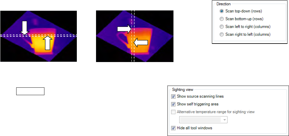
from 4 different direction options provided (see below image X scan top-down (rows) and scan bottom-up
(rows) and image Y scan left to right (columns) and scan right to left (columns).
6.2.6. Layout Configuration of the Sighting View Mode
You can make further modifications to the Sighting view mode
using Extended menu. If you go to Sighting view you can
define following modifications: Show source scanning lines,
show self triggering area or Hide all tool windows.
Alternative temperature range for sighting view option
enables switching to temperature range different from the one
used for the measurement. It is sometimes helpful to configure
the linescanner when process is stopped using one
temperature range where as different temperature range is defined to examine running process.
The displayed linescanner sighting views
visualize the 4 possibilites how to capture
and finally represent multiple lines in the
linescanner view