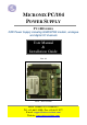
MICRONIX PC/104 POWER SUPPLY PV-1800 SERIES 20W Power Supply including GSM/GPRS modem, analogue and digital I/O channels User Manual & Installation Guide VER. 1.0 DOC: M5258DM Micro Technic A-S • Denmark • Tel. +45 6615 3000 • Fax +45 6615 3077 E-mail: support@micro-technic.com Website: www.micro-technic.
Users Manual & Installation Guide PV- 1800: Power supply module with GSM MODEM Table of contents GENERAL INFORMATION.......................................................................................................................................... 3 ORDERING CODES ........................................................................................................................................................... 3 ANALOGUE CONFIGURATIONS ........................................................
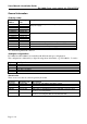
Users Manual & Installation Guide PV- 1800: Power supply module with GSM MODEM General information Ordering codes Model Ordering number code PV-1800-S-1 PV-1800-S-2 PV-1800-S-3 PV-1800-S-4 PV-1800-S-5 PV-1800A-S-1 PV-1800A-S-2 PV-1800A-S-3 PV-1800A-S-4 PV-1800A-S-5 PV-1820-S PV-1820A-S PV-1830-S PV-1830A-S 016.104.088 016.104.115 016.104.116 016.104.117 016.104.101 016.104.109 016.104.118 016.104.119 016.104.120 016.104.121 016.104.089 016.104.123 016.104.096 016.104.
Users Manual & Installation Guide PV- 1800: Power supply module with GSM MODEM Description The PV-1800, the fully equipped model, offers the following features: • a PC/104 20W power supply +5V, 4A. • a dual band GSM/GPRS modem (Sony Ericsson GM47) • 8 isolated analogue inputs, 12 bit • 8 digital inputs, opto-isolated • 7 digital outputs, opto-isolated • one RS232 serial port • non-isolated simple I/O’s. Block diagram % 0 + . 12 . %*&$ %-# '$ + + . ,- %! %- ,-# ( & $/ ( */' + . .
Users Manual & Installation Guide PV- 1800: Power supply module with GSM MODEM The digital inputs are bipolar isolated with a max. input voltage of +/- 30V. There are 7 isolated digital P-channel outputs each capable of driving up to 0.5A. The load current must be supplied from an external voltage source not exceeding 30V. The UPS connector contains control signals that can be used with external UPS circuitry.
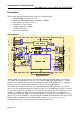
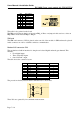
Users Manual & Installation Guide PV- 1800: Power supply module with GSM MODEM )=&6 5> 8 *0 Power Supply The on-board power supply consists of a synchronous step-down switching regulator with an efficiency of 85-95%, depending on input voltage and load current. At nominal input voltage (24V DC) and a load current of 2A the efficiency is 92%. A green status LED, placed on the rear side of the PCB, is on when the +5V is present. The connector for the power input is a 2 pole pin header from Molex.
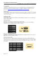
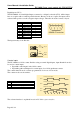
Users Manual & Installation Guide ST1 2 0 0 1 1 0 0 1 1 3 0 1 0 1 0 1 0 1 Base address COM_A Disabled 2C8 2D8 2E8 (COM4) 2F8 (COM2) 3D8 3E8 (COM3) 3F8 (COM1) . %- %-# '$ + 1 0 0 0 0 1 1 1 1 PV- 1800: Power supply module with GSM MODEM ,,-# This table is also printed on the board. The IRQ used for the modem is set in section IRQ_A. Place one jumper in this section to select an IRQ number in the interval IRQ3 to IRQ15. SIM card The SIM card connector (CN9) is placed on the rear side of the module.
Users Manual & Installation Guide PV- 1800: Power supply module with GSM MODEM AT commands All functions of the modem are carried out by AT commands from a computer application. For documentation of the AT command set please see “Integrators Manual” for GM47 from Sony Ericsson, at http://www.eurodis.com/wireless/htm/suppliers_sonyericsson.asp Modem on/off The PV-1800 has circuitry that automatically turns the modem on after a system reset, by activating its ON/OFF input.
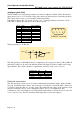
Users Manual & Installation Guide PV- 1800: Power supply module with GSM MODEM Analogue inputs (CN5) The PV-1800 has 8 isolated analogue inputs accessible in a 10pin box header (CN5). Beside these inputs, there is also a +3.3V isolated voltage with common ground reference as the analogue inputs. This voltage can be used to power external conditioning circuitry. Depending on the model – see section ordering codes – each input will have a full scale of 2.5V, 5.0V, 10V, or 20mA.
Users Manual & Installation Guide PV- 1800: Power supply module with GSM MODEM Digital inputs (CN 1) The PV1800 has 8 isolated digital inputs connected to a 10-pin box header (CN1). All the inputs have ac-couplers with a common ground reference. Because of the ac-couplers, the inputs can be activated with positive as well as negative input voltages.
Users Manual & Installation Guide PV- 1800: Power supply module with GSM MODEM Digital outputs (CN2) The PV1800 has 7 isolated digital outputs connected to a 10pin box header (CN2). The outputs are configured as PNP outputs with their transistors connected to an external supply voltage (+V_EXT).
Users Manual & Installation Guide PV- 1800: Power supply module with GSM MODEM UPS signals (CN7) The PV-1800 has signals that, combined with external circuitry, can be used to implement a UPS function. There is an input for turning off the 20W power supply (SWITCHER_OFF), two status inputs (UPS_STATUS1 and UPS_STATUS2), and an output (UPS_PWROFF) that can tell the external circuitry to turn off power after a programmable delay.
Users Manual & Installation Guide PV- 1800: Power supply module with GSM MODEM Internal registers Address Base+0 Base+1 Base+2 Base+3 Base+4 Base+5 Base+6 Base+7 Base+8 Base+9 Base+0Ah Base+0Bh Base+0Ch Base+0Dh Base+0Eh Base+0Fh Access Read only Read only Read/write Read only Read only Read only Read/write Read/write Read/write Read/write Read/write Read/write - Name REG_SIGN REG_MODEL REG_DIGOUT REG_DIGIN REG_CNTLO REG_CNTHI REG_CNTMODE REG_MODEM REG_UPS REG_UPSSHDN REG_ADCLO REG_ADCHI reserved reserv
Users Manual & Installation Guide PV- 1800: Power supply module with GSM MODEM REG_CNTMODE (base+6): Counter configuration (read/write) The counter starts at 0000h after system reset. It cannot be reset or reloaded from software.
Users Manual & Installation Guide PV- 1800: Power supply module with GSM MODEM REG_ADCLO (base+0Ah): ADC command, status, and result low byte (read/write) Writing to this register starts a new A/D conversion. You should only do this when the ADC is idle. Command bits: 0000dccc d: 0:single-ended, 1=differential ccc: Channel.
Users Manual & Installation Guide PV- 1800: Power supply module with GSM MODEM Technical data Power supply Input voltage (nominal) Input voltage (MAX) Output voltage External load UPS interface: 4 pins in CN7 GSM-modem: Modem type SIM card interface Frequency range Maximum RF output power Antenna impedance Antenna connector type Supported I/Os (using AT commands) 3 Analogue inputs * 1 Analogue output * 4 general purpose digital inputs * COM ports: Number of ports Addressing range IRQs supported Connector
Users Manual & Installation Guide Max input voltage Counter input Max counting rate Connector type Digital outputs: Number of channels Max load current Max voltage Protection Connector type Environmental specifications: Operating temperature: Storage temperature: Humidity: Cyclic humidity: Vibration: Sustained vibration: Shock Size (W x L x H) Weight: PV- 1800: Power supply module with GSM MODEM Input high voltage: 10 – 24V 30V, current limiting resistor = 3.
Users Manual & Installation Guide Mechanical Layout PV- 1800: Power supply module with GSM MODEM This schematic shows the dimensions for PV-1800. All dimensions are in mm.
Users Manual & Installation Guide PV- 1800: Power supply module with GSM MODEM Installation guide Precautions to ESD Please note that the Micronix PV modules must be handled with respect to ESD (Electrostatic Discharge). Electrostatic Discharge to the PV modules must be avoided. Before removing the module from the protection bag, the user must be discharged using a grounded wrist ribbon. Settings and connections A typical setup procedure involves these steps: 1. Perform settings of: • Base address.