MBS-GPS-SS2-5HZ Novatel SuperStar II PC/104 GPS Module User’s Manual MICROBEE SYSTEMS CORPORATION 21723 North Meadowview Court Colbert, WA 99005 Tech. Support: 256–426–2431 www.microbee-systems.com support@microbee-systems.com CAGE Code 3DPE9 COPYRIGHT 2005 MicroBee Systems Corporation. All rights reserved. However, any part of this document may be reproduced, provided that MicroBee Systems Corporation is cited as the source.
NOTICE TO USER The information contained in this manual is believed to be correct. However, MicroBee Systems assumes no responsibility for any of the circuits described herein, conveys no license under any patent or other right, and makes no representations that the circuits are free from patent infringement. MicroBee Systems makes no representation or warranty that such applications will be suitable for the use specified without further testing or modification.
PREFACE This manual is a guide to the proper configuration, installation, and operation of your MBS-GPSSS2-5HZ Interface. For setup and operation of the Novatel SSII Manuals included with this product. You can use your MBS-GPS-SS2-5HZ card in conjunction with other PC/104 expansion cards, tailoring your system for a wide variety of applications. TECHNICAL SUPPORT MicroBee Systems is committed to supporting our products.
deep. This means that instead of an interrupt generated every 15 characters one could be generated only once per message greatly reducing overhead on the host processor to handle interrupt servicing. The unit incorporates the 16 bit PC/104 ISA connector so 16 bit devices can be placed on the stack after the radio. Also interrupts 10, 11, 14 and 15 are accessed thru this connector.
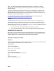
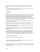
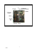
INSTALLATION Before installing the MBS-GPS-SS2-5HZ GPS Module, refer to Figure 1 for the location of various connectors and jumpers. Interrupt Select Jumpers, JP3 & JP 4: JP3 is used to select the IRQ Level for the DATA port. IRQ's 3, 4, 5, 6, 7, 9, 10, 11, 12, 14 and 15 are supported. Simply select the desired IRQ level by moving the jumper to the appropriate position. Default configuration for JP3 is IRQ4 which is standard for COM1. Default configuration for JP4 is IRQ3 which is standard for COM 2.
GPS Identification Bits, JP5 and JP6 This module was designed to be used with multiple data sources through the use of both mezzanine cards to replace the Novatel SSII as well as multiple serial peripherals accessible from the EXT GPS/Data port, J7. To allow user software identification of the type of GPS/ Module connected/installed on the MBS-GPS-SS2-5HZ JP5 and JP6 are available for use as identification bits. ID bits are read by polling the DCD, DSR and CTS bits of the Differential Port.
In position 2-3 the data, 1 PPS inversion is based upon Jumper JP10A, not the RTS bit of the Data Port. JP10A 2-3 un-inverts the 1PPS source and JP10A 1-2 inverts the 1PPS source. NOTE: Refer to the Novatel Super Star II GPS OEM Module Users Manual and Firmware Manuals for proper operation and setup of the onboard GPS. Status Monitoring: Overview: Several unusual status features are available.
J6.3: TTL level 1PPS output. It is identical to J6.1 except it is TTL level. J6.4: BAT IN is a optional input for an EXT battery to backup warm fix information on the Novatel SS2. The Novatel SS2 has a charge storage device to maintain this information for up to 1 week. Longer storage requires a battery. This battery is diode isolated and should range from 3.3 to a MAXIMUM of 4.5 volts. This should accommodate most common CMOS backup batteries with 4.5 V being nominal. This is battery type dependant.
Figure 1, Jumper Layout 9 Rev A
WARRANTY MicroBee Systems Corporation (MicroBee), warrants that it’s standard hardware products will be free from defects in materials and workmanship under normal use and service a period of one year from date of purchase. MicroBee’s obligation under this warranty shall not begin until Buyer returns the defective product, freight prepaid to MicroBee’s facility or another specified location.
RETURNING A PRODUCT FOR REPAIR Upon determining that repair services are required, the customer must: 1. Obtain an RMA (Return Material Authorization) number from the Customer Service Department, 256-426-2431. 2. If the request is for an out of warranty repair, a purchase order number or other acceptable information must be supplied by the customer. 3. Include a list of problems encountered along with your name, address, telephone, and RMA number. 4. Carefully package the product in an antistatic bag.