
User's Guide


Table Of Contents
- Introduction
- Features
- Table of Contents
- 1. Quick References
- 2. Kit Overview
- 3. Kit Setup
- 4. CARS Kit PC Evaluation Utility
- 5. System Operation
- 6. Programming Instructions
- 7. XPRO USB Driver Installation
- 8. Document Revision History
- The Microchip Website
- Product Change Notification Service
- Customer Support
- Microchip Devices Code Protection Feature
- Legal Notice
- Trademarks
- Quality Management System
- Worldwide Sales and Service
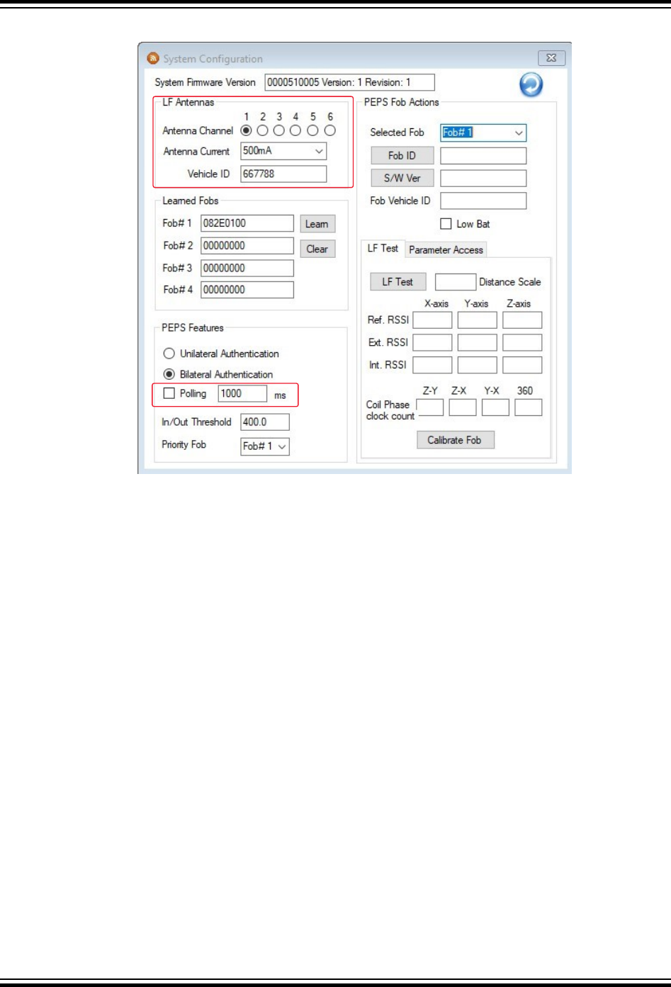
Figure 5-15. LF Antennas and Polling
4. Select the desired LF Antenna Current.
5. Enter the polling interval value in milliseconds (for example, 1000, meaning the LF wake-up signal is
transmitted every one second).
Note: 500 ms is the minimum allowable interval.
6. Select the “Polling” check box to enable polling and ensure that the LEDs on the fob blink each time the new
wake-up signal is received.
7. Type in a new Vehicle ID (for example, 887766), click on any other field within the window and ensure that the
LEDs on the fob no longer blink. This demonstrates that the fob only wakes up for the vehicle it was paired to.
8. Type in the original Vehicle ID: 667788.
9. Deselect the “Polling” check box to disable polling.
5.3.7 PEPS Communication
The PEPS communication functionality can be tested using the CARS PC application running on the host PC as
follows:
1. If not done already, follow the procedure detailed in 4. CARS Kit PC Evaluation Utility.
2. If not done already, follow the calibration procedure detailed in 5.3.5 Fob Calibration Process .
3. Position the fob at the desired distance from the LF antenna module that will be used for the fob’s in/out
threshold.
4. Navigate to View > PEPS Messaging to open the PEPS Message Status window, as shown in Figure 5-4.
5. Click the PEPS UA button and, after the authentication sequence completes, note the value of the number in
the “Distance Scale” field of the PEPS Message Status window. Enter this value in the “In/Out Threshold” field
of the System Configuration window (see Figure 5-15).
6. Move the fob closer to the LF antenna module.
7. Click the PEPS UA button within the PEPS Message Status window to execute the unilateral authentication
sequence.
ATAN0219
System Operation
© 2020 Microchip Technology Inc.
User Guide
DS50003051A-page 30
Microchip Confidential: For Release Only Under Non-Disclosure Agreement (NDA)