
User's Guide


Table Of Contents
- Introduction
- Features
- Table of Contents
- 1. Quick References
- 2. Kit Overview
- 3. Kit Setup
- 4. CARS Kit PC Evaluation Utility
- 5. System Operation
- 6. Programming Instructions
- 7. XPRO USB Driver Installation
- 8. Document Revision History
- The Microchip Website
- Product Change Notification Service
- Customer Support
- Microchip Devices Code Protection Feature
- Legal Notice
- Trademarks
- Quality Management System
- Worldwide Sales and Service
6. Programming Instructions
Specific firmware (Flash) and, in some devices, configuration settings (EEPROM) are required to operate the system.
These are found in the MCU (ATSAMC21-XPRO) and the RF transceiver (ATA5831-XPRO) on the vehicle side. The
fob requires its own PEPS, IMMO and RKE firmware and configuration files. The following list describes exactly what
type of files are needed for each device:
• Vehicle side:
– ATSAMC21-XPRO: PEPS, IMMO and RKE firmware and configuration in Flash
– ATA5831-XPRO: PEPS and RKE configuration in the EEPROM
• Fob side:
– ATAB5702A fob board: PEPS, IMMO and RKE firmware in Flash and configuration in the EEPROM
Note: All devices within this system are shipped unprogrammed; therefore, the programming procedure is described
in the following sections. Programming is also required when the revised ATAK51005-V1 tool package software is
available for download from www.microchip.com/developmenttools/ProductDetails/ATAK51005-V1 or when the
source code has been modified or when a device becomes erratic or unresponsive in behavior.
6.1 Programming the ATA5702 on the ATAB5702A Fob Board
To program the ATA5702 on the ATAB5702A fob board, first connect the programmer (for example, Atmel-ICE or
JTAGICE3) to the ISP header located near the center of the board. The following steps use an Atmel-ICE
programmer and the ISP interface for programming:
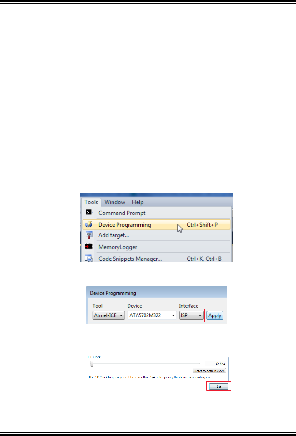
1. In Atmel Studio 7, navigate to Tools > Device Programming.
Figure 6-1. Device Programming
2. Select the Tool, Device and Interface, as shown in the following figure, then click Apply.
Figure 6-2. ATA5702 Device Selection
3. Ensure that the ISP frequency is less than 100 kHz. Click Set.
Figure 6-3. ATA5702 ISP Clock Frequency
4. Click the Read button to ensure that the signature matches the selected device.
ATAN0219
Programming Instructions
© 2020 Microchip Technology Inc.
User Guide
DS50003051A-page 33
Microchip Confidential: For Release Only Under Non-Disclosure Agreement (NDA)