
User's Guide


Table Of Contents
- Introduction
- Features
- Table of Contents
- 1. Quick References
- 2. Kit Overview
- 3. Kit Setup
- 4. CARS Kit PC Evaluation Utility
- 5. System Operation
- 6. Programming Instructions
- 7. XPRO USB Driver Installation
- 8. Document Revision History
- The Microchip Website
- Product Change Notification Service
- Customer Support
- Microchip Devices Code Protection Feature
- Legal Notice
- Trademarks
- Quality Management System
- Worldwide Sales and Service
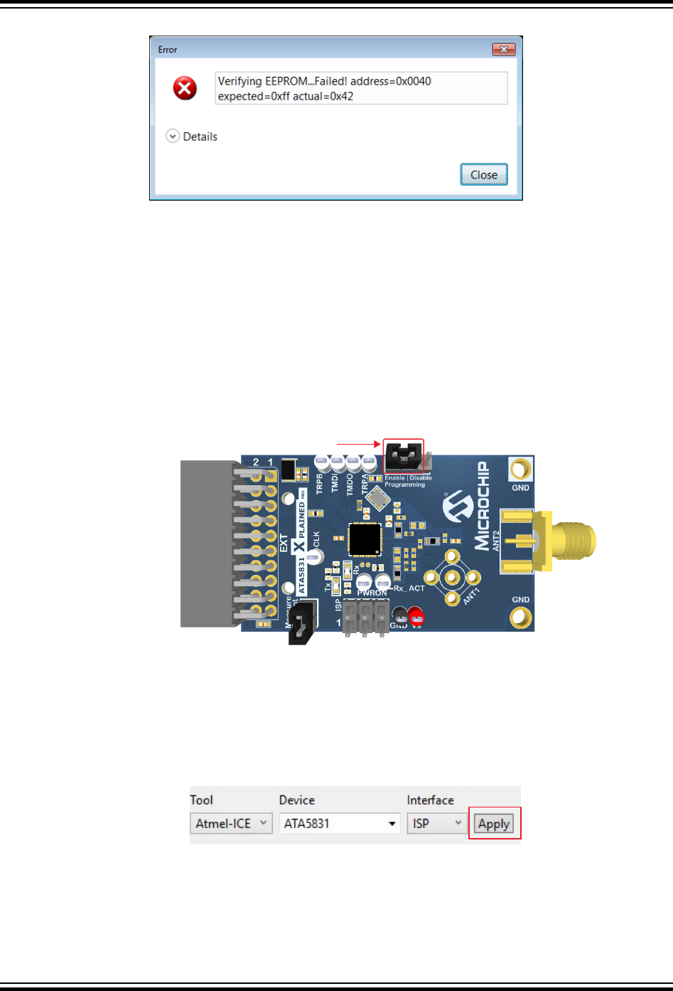
Figure 6-7. EEPROM Verification Failure
6.2 Programming the ATA5831 on the ATA5831-XPRO Board
Perform the following steps to program the ATA5831 on the ATA5831-XPRO board:
1. Insert the ATA5831-XPRO board in the EXT1 connector on the ATSAMC21-XPRO board.
2. Connect the micro-USB plug to the USB connector on the ATSAMC21-XPRO board, then connect the other
end of the USB cable to an open USB port on the PC.
3. Connect the programmer (for example, Atmel-ICE or JTAGICE3) to the ISP header located near the edge of
the board.
4. Place a jumper on the Enable position of the Enable | Disable Programming header, the two pins closest to the
EXT connector, as shown in the following figure.
Figure 6-8. Jumper Placement on the ATA5831-XPRO Board for EEPROM Programming
Jumper on Enable Position
Note: For better clarity, the ATSAMC21-XPRO board is not shown.
The following steps use an Atmel-ICE programmer and the ISP interface for programming:
1. In Atmel Studio 7, navigate to Tools > Device Programming.
2. Select the Tool, Device and Interface, as shown in the following figure, then click Apply.
Figure 6-9. ATA5831 Device Selection
3. Ensure that the ISP frequency is less than 100 kHz. Click Set.
ATAN0219
Programming Instructions
© 2020 Microchip Technology Inc.
User Guide
DS50003051A-page 35
Microchip Confidential: For Release Only Under Non-Disclosure Agreement (NDA)