
User's Guide
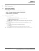
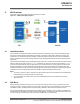
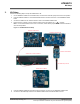
Table Of Contents
- Introduction
- Features
- Table of Contents
- 1. Quick References
- 2. Kit Overview
- 3. Kit Setup
- 4. CARS Kit PC Evaluation Utility
- 5. System Operation
- 6. Programming Instructions
- 7. XPRO USB Driver Installation
- 8. Document Revision History
- The Microchip Website
- Product Change Notification Service
- Customer Support
- Microchip Devices Code Protection Feature
- Legal Notice
- Trademarks
- Quality Management System
- Worldwide Sales and Service
3. Kit Setup
Perform the following steps to set up the ATAK51005-V1 kit:
1. On the ATSAMC21-XPRO microcontroller board, ensure that the VCC-SEL jumper is set to the 5.0V position.
2. Insert the ATA5291-XPRO LF coil driver/immobilizer board in the EXT3 connector on the ATSAMC21-XPRO
board.
3. Connect the ATAB-LFTX LF antenna module to Ant0 on the ATA5291-XPRO board.
4. Ensure that the J1 jumper on the LF antenna module is set to the inductor only ( ) position.
Note: For use of the antenna on the Ant1-7 connectors, ensure that the jumper on the LF antenna module is
set to the LCR position.
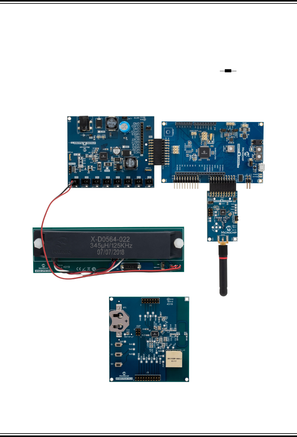
Figure 3-1. ATAK51005-V1 Kit Setup
ATA5291-XPRO Board
ATSAMC21-XPRO Board
ATA5831-XPRO Board
ATAB5702A Fob Board
ATAB-LFTX LF Antenna Module
UHF SMA Whip Antenna
5. Insert the ATA5831-XPRO RF transceiver board in the EXT1 connector on the ATSAMC21-XPRO board.
6. Connect the UHF SMA whip antenna to the ATA5831-XPRO board at the ANT2 SMA connector.
ATAN0219
Kit Setup
© 2020 Microchip Technology Inc.
User Guide
DS50003051A-page 7
Microchip Confidential: For Release Only Under Non-Disclosure Agreement (NDA)