
User's Guide


Table Of Contents
- Introduction
- Features
- Table of Contents
- 1. Quick References
- 2. Kit Overview
- 3. Kit Setup
- 4. CARS Kit PC Evaluation Utility
- 5. System Operation
- 6. Programming Instructions
- 7. XPRO USB Driver Installation
- 8. Document Revision History
- The Microchip Website
- Product Change Notification Service
- Customer Support
- Microchip Devices Code Protection Feature
- Legal Notice
- Trademarks
- Quality Management System
- Worldwide Sales and Service
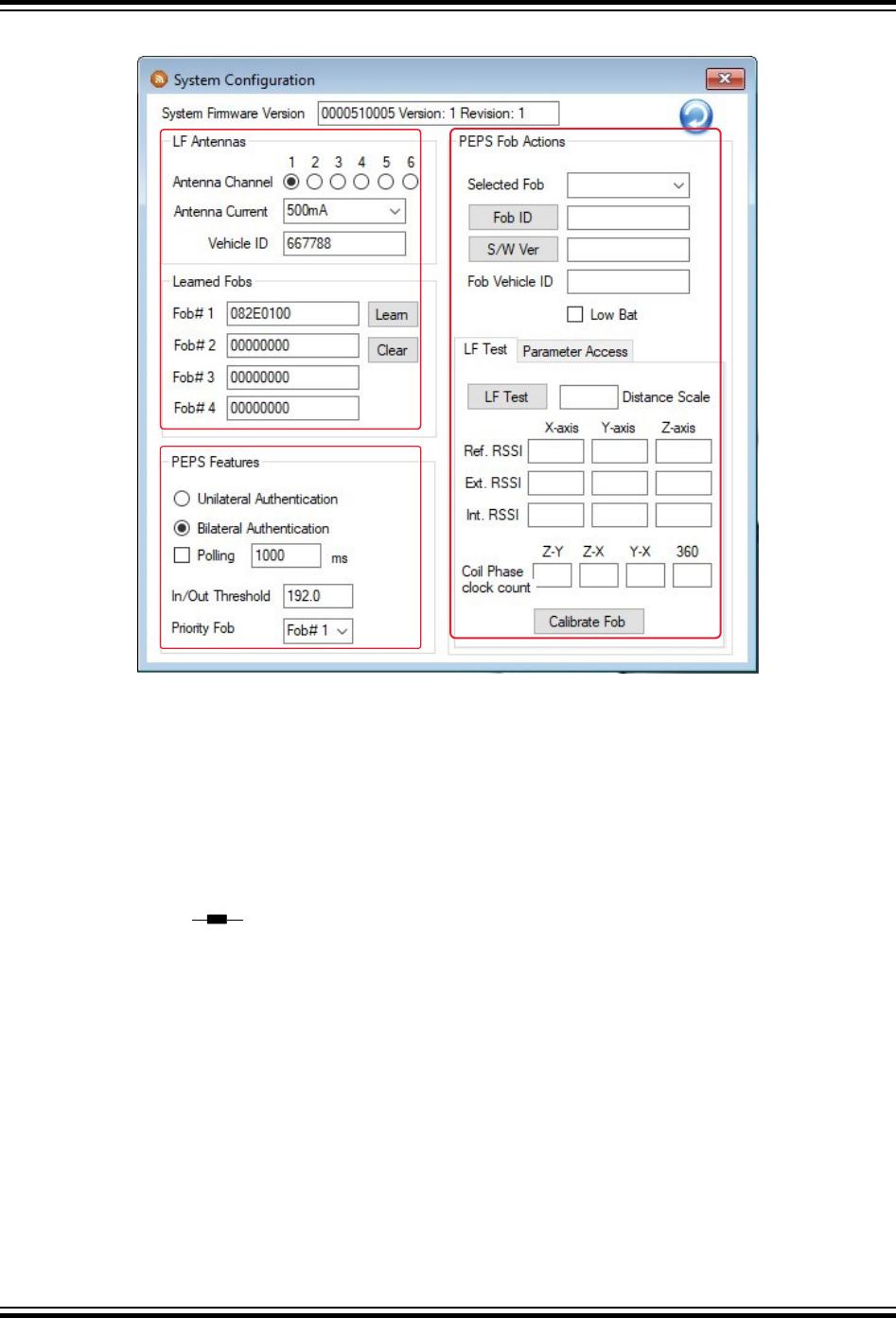
Figure 5-3. System Configuration Window
The System Configuration window contains the following sections and associated data fields:
• “LF Antennas” – This section includes controls used to select the antenna channel and the current and
associated vehicle ID.
– “Antenna Channel” – Selecting any of these radio buttons assigns which antenna channel is used to send
the LF message from the vehicle. The LF antenna module must be connected to the corresponding port on
the ATA5291-XPRO board for this to function properly. Note that the Ant connector number on the
ATA5291-XPRO board starts at Ant0 while the antenna channel displayed on the CARS PC application
starts with Antenna Channel 1. As a result, Antenna Channel 1 on the PC application corresponds with
Ant0 on the board. This offset count continues for all six antenna channels.
Note: When antenna channel 1 is used, ensure that the J1 jumper on the LF antenna module is set to the
inductor only (
) position. When channels 2 through 6 are used, ensure the J1 jumper on the LF
antenna module is set to the LCR option.
– “Antenna Current” – This drop-down list determines the amount of current flowing in the LF antenna during
the LF message. This is directly related to the field strength at a given distance from the antenna.
Therefore, any change to this value has a direct impact on the performance of the localization during
PEPS.
– “Vehicle ID” – Sets the wake-up value transmitted with the LF message. Only fobs that are looking for this
value wake up and respond. The vehicle ID is set in the fob during the learn procedure and is user-
definable.
• “Learned Fobs” – This section lists up to four individual fob IDs paired with the system and saved in memory.
– “Learn” – This button performs the initial pairing of any new fobs to the system using the immobilizer LF
field provided by the LF antenna module. For details on the learn procedure, see 4.4 Initial Configuration of
the CARS Kit PC Evaluation Utility .
– “Clear” – This button erases all the saved fob secret keys and configuration data from the system memory.
Note: The system does not have full functionality until a fob is paired.
ATAN0219
System Operation
© 2020 Microchip Technology Inc.
User Guide
DS50003051A-page 16
Microchip Confidential: For Release Only Under Non-Disclosure Agreement (NDA)