
User's Guide


Table Of Contents
- Introduction
- Features
- Table of Contents
- 1. Quick References
- 2. Kit Overview
- 3. Kit Setup
- 4. CARS Kit PC Evaluation Utility
- 5. System Operation
- 6. Programming Instructions
- 7. XPRO USB Driver Installation
- 8. Document Revision History
- The Microchip Website
- Product Change Notification Service
- Customer Support
- Microchip Devices Code Protection Feature
- Legal Notice
- Trademarks
- Quality Management System
- Worldwide Sales and Service
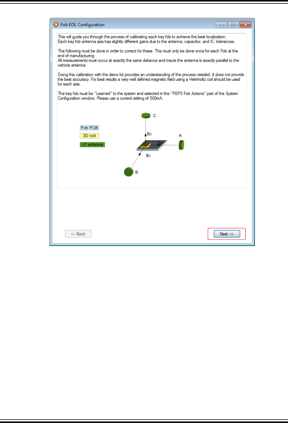
Figure 5-7. FOB EOL Configuration Window
5. Position the LF antenna module and the fob (as shown in the following figure) to align the X-axis of the fob
with the LF antenna module axis, then click the Measure button. This measures the current X-axis RSSI signal
amplitude and updates the result to the “Peak RSSI” field for the X-axis. Click the Measure button several
times to ensure the peak value is stable.
6. Click the Next button.
ATAN0219
System Operation
© 2020 Microchip Technology Inc.
User Guide
DS50003051A-page 22
Microchip Confidential: For Release Only Under Non-Disclosure Agreement (NDA)