
User manual


MPLAB
®
REAL ICE
™
In-Circuit Emulator User’s Guide
DS51616B-page 116 © 2008 Microchip Technology Inc.
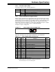
The electrical specifications for logic probes are listed in Table 12-2.
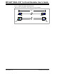
12.6 STANDARD COMMUNICATION HARDWARE
For standard emulator communication with a target (Section 2.3.1 “Standard
Communication”), use the standard driver board.
To use this type of communication with a header board, you may need a device-specific
Processor Pak, which includes an 8-pin connector header board containing the desired
ICE/ICD device and a standard adapter board (8-pin to 6-pin connection).
For more on available header boards, see the “Header Board Specification”
(DS51292).
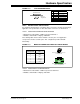
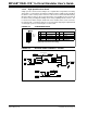
12.6.1 Standard Driver Board
The standard driver board is the main interface to the target processor. It contains the
connections to the high voltage (V
PP), VDD sense lines, and clock and data connections
required for programming and connecting with the target devices.
The V
PP high-voltage lines can produce a variable voltage that can swing from 14 to 0
volts to satisfy the voltage requirements for the specific emulation processor.
The V
DD sense connection draws very little current from the target processor. The
actual power comes from the MPLAB REAL ICE in-circuit emulation system as the V
DD
sense line is used as a reference only to track the target voltage. The V
DD connection
is isolated with an optical switch.
The clock and data connections are interfaces with the following characteristics:
• Clock and data signals are in high-impedance mode (even when no power is
applied to the MPLAB REAL ICE in-circuit emulator system)
• Clock and data signals are protected from high voltages caused by faulty targets
systems, or improper connections
• Clock and data signals are protected from high current caused from electrical
shorts in faulty target systems
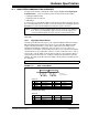
TABLE 12-2: LOGIC PROBE ELECTRICAL SPECIFICATIONS
Logic Inputs VIH = VDD x 0.7V (min)
VIL = VDD x 0.3V (max)
Logic Outputs VDD = 5V VDD = 3V VDD = 2.3V VDD = 1.65V
V
OH = 3.8V min VOH = 2.4V min VOH = 1.9V min VOH = 1.2V min
VOL = 0.55V max VOL = 0.55V max VOL = 0.3V max VOL = 0.45V max
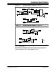
Note: Older header boards used a 6-pin (RJ-11) connector instead of an 8-pin
connector, so these headers may be connected directly to the emulator.
Note: When using the standard driver board, the rate for real-time streaming data
and tracing is limited to 15 MIPS.