AR1000 Series Resistive Touch Screen Controller Data Sheet 2009-2012 Microchip Technology Inc.
Note the following details of the code protection feature on Microchip devices: • Microchip products meet the specification contained in their particular Microchip Data Sheet. • Microchip believes that its family of products is one of the most secure families of its kind on the market today, when used in the intended manner and under normal conditions. • There are dishonest and possibly illegal methods used to breach the code protection feature.
AR1000 SERIES RESISTIVE TOUCH SCREEN CONTROLLER AR1000 Series Resistive Touch Screen Controller Special Features: Touch Sensor Support: • • • • • • • • • RoHS Compliant Power-Saving Sleep mode Industrial Temperature Range Built-in Drift Compensation Algorithm 128 Bytes of User EEPROM 4-Wire, 5-Wire and 8-Wire Analog Resistive Lead-to-Lead Resistance: 50-2,000typical) Layer-to-Layer Capacitance: 0-0.
AR1000 SERIES RESISTIVE TOUCH SCREEN CONTROLLER Table of Contents 1.0 Device Overview .......................................................................................................................................................................... 5 2.0 Basics of Resistive Sensors ......................................................................................................................................................... 7 3.0 Hardware.....................................................
AR1000 SERIES RESISTIVE TOUCH SCREEN CONTROLLER 1.0 DEVICE OVERVIEW 1.1 The Microchip mTouchTM AR1000 Series Resistive Touch Screen Controller is a complete, easy to integrate, cost-effective and universal touch screen controller chip. The AR1000 Series has sophisticated proprietary touch screen decoding algorithms to process all touch data, saving the host from the processing overhead.
AR1000 SERIES RESISTIVE TOUCH SCREEN CONTROLLER TABLE 1-1: PIN DESCRIPTIONS Pin SSOP, SOIC QFN Function Description/Comments 1 18 VDD Supply Voltage 2 19 M1 Communication Selection 3 20 SY- Sense Y- (8-wire). Tie to VSS, if not used. 4 1 M2 4/8-wire or 5-wire Sensor Selection 5 2 WAKE 6 3 SIQ LED Drive/SPI Interrupt. No connect, if not used. 7 4 SY+ Sense Y+ (8-wire). Tie to VSS, if not used. 8 5 SS Slave Select (SPI). Tie to VSS, if not used.
AR1000 SERIES RESISTIVE TOUCH SCREEN CONTROLLER 2.0 BASICS OF RESISTIVE SENSORS 2.1 Terminology Bus Bars or Silver Frit electrically connect the ITO on the flex and stable layers to the sensor’s interface tail. Bus bars are typically screen printed silver ink. They are typically much lower in resistivity than the ITO. X-Axis is the left and right direction on the touch sensor. ITO (Indium Tin Oxide) is the resistive coating that makes up the active area of the touch sensor.
AR1000 SERIES RESISTIVE TOUCH SCREEN CONTROLLER 2.3 4-Wire Sensor A 4-wire resistive touch sensor consists of a stable and flex layer, electrically separated by spacer dots. The layers are assembled perpendicular to each other. The touch position is determined by first applying a voltage gradient across the flex layer and using the stable layer to measure the flex layer’s touch position voltage.
AR1000 SERIES RESISTIVE TOUCH SCREEN CONTROLLER 2.4 8-Wire Sensor An 8-wire resistive touch sensor consists of a stable and flex layer, electrically separated by spacer dots. The layers are assembled perpendicular to each other. The touch position is determined by first applying a voltage gradient across the flex layer and using the stable layer to measure the flex layer’s touch position voltage.
AR1000 SERIES RESISTIVE TOUCH SCREEN CONTROLLER 2.5 5-Wire Sensor A 5-wire resistive touch sensor consists of a flex and stable layer, electrically separated by spacer dots. The touch position is determined by first applying a voltage gradient across the stable layer in the X-axis direction and using the flex layer to measure the axis touch position voltage.
AR1000 SERIES RESISTIVE TOUCH SCREEN CONTROLLER 3.0 HARDWARE 3.1 Main Schematic A main application schematic for the SOIC/SSOP package pinout is shown in Figure 3-1. See Figure 1-2 for the QFN package pinout. FIGURE 3-1: MAIN SCHEMATIC (SOIC/SSOP PACKAGE PINOUT) 2009-2012 Microchip Technology Inc.
AR1000 SERIES RESISTIVE TOUCH SCREEN CONTROLLER 3.2 4, 5, 8-Wire Sensor Selection 3.3 The desired sensor type of 4/8-wire or 5-wire is hardware selectable using pin M2. TABLE 3-1: Type 4/8-WIRE vs. 5-WIRE SELECTION M2 pin 4/8-wire VSS 5-wire VDD If 4/8-wire has been hardware-selected, then the choice of 4-wire or 8-wire is software-selectable via the TouchOptions Configuration register. 4-Wire Touch Sensor Interface Sensor tail pinouts can vary by manufacturer and part number.
AR1000 SERIES RESISTIVE TOUCH SCREEN CONTROLLER 3.4 5-Wire Touch Sensor Interface Sensor tail pinouts can vary by manufacturer and part number. Ensure sensor tail pins for one pair of diagonally related sensor corners are connected to the controller’s X-/X+ pins and the tail pins for the other pair of diagonally related corners are connected to the controller’s Y-/Y+ pins. The controller’s X-/X+ and Y-/Y+ pin pairs do not need to connect to a specific sensor axis.
AR1000 SERIES RESISTIVE TOUCH SCREEN CONTROLLER 3.5 8-Wire Touch Sensor Interface Sensor tail pinouts can vary by manufacturer and part number. Ensure both sensor tail pins for one sensor axis (layer) are connected to the controller’s X-/X+ pins and the tail pins for the other sensor axis (layer) are connected to the controller’s Y-/Y+ pins. The controller’s X-/X+ and Y-/Y+ pin pairs do not need to connect to a specific sensor axis.
AR1000 SERIES RESISTIVE TOUCH SCREEN CONTROLLER 3.6 Status LED 3.8 ESD Considerations The LED and associated resistor are optional. ESD protection is shown on the 4-wire, 5-wire, and 8-wire interface applications schematics. FIGURE 3-5: The capacitance of alternate ESD diodes may adversely affect touch performance. A lower capacitance is better. The PESD5V0S1BA parts shown in the reference design have a typical capacitance of 35 pF.
AR1000 SERIES RESISTIVE TOUCH SCREEN CONTROLLER NOTES: DS41393B-page 16 Preliminary 2009-2012 Microchip Technology Inc.
AR1000 SERIES RESISTIVE TOUCH SCREEN CONTROLLER I2CTM COMMUNICATIONS 4.0 The AR1021 is an I2C slave device with a 7-bit address of 0x4D, supporting up to 400 kHz bit rate. A master (host) device interfaces with the AR1021. I2C Hardware Interface 4.1 A summary of the hardware interface pins is shown below in Table 4-1.
AR1000 SERIES RESISTIVE TOUCH SCREEN CONTROLLER I2C Pin Voltage Level Characteristics 4.2 I2C PIN VOLTAGE LEVEL CHARACTERISTICS TABLE 4-2: Function Pin Input Output SCL/SCK SCL/SCK/TX VSS ≤ VIL≤ 0.2*VDD 0.8*VDD ≤ VIH ≤ VDD — SDO SDO — VSS ≤ VOL(1) ≤ (1.2V – 0.15*VDD)(2) (1.25*VDD – 2.25V)(3) ≤ VOH(1) ≤ VDD SDA SDI/SDA/RX VSS ≤ VIL ≤ 0.2*VDD 0.8*VDD ≤ VIH ≤ VDD Open-drain Note 1: 2: 3: 4.3 These parameters are characterized but not tested. At 10 mA. At –4 mA.
AR1000 SERIES RESISTIVE TOUCH SCREEN CONTROLLER 6. Master receives eight data bits (MSb first) presented on SDA by the AR1021, at eight sequential master clock (SCL) cycles. The data is latched out on SCL falling edges to ensure it is valid during the subsequent SCL high time. 7. If data transfer is not complete, then: - Master acknowledges (ACK) reception of the eight data bits by presenting a low on SDA, followed by a low-high-low on SCL. - Go to step 5. 8.
AR1000 SERIES RESISTIVE TOUCH SCREEN CONTROLLER 4.8 Touch Report Protocol Touch coordinates, when available, are provided to the master by the AR1021 in the following protocol (See Figure 4-3). FIGURE 4-3: I2C TOUCH REPORT PROTOCOL Note that the IRQ signal shown above occurs on the SDO pin of the AR1021. 4.9 Command Protocol The master issues supported commands to the AR1021 in the following protocol. Below is an example of the ENABLE_TOUCH command (see Figure 4-4).
AR1000 SERIES RESISTIVE TOUCH SCREEN CONTROLLER 5.0 SPI COMMUNICATIONS SPI operates in Slave mode with an Idle low SCK and data transmitted on the SCK falling edge. 5.1 SPI Hardware Interface A summary of the hardware interface pins is shown below in Table 5-1.
AR1000 SERIES RESISTIVE TOUCH SCREEN CONTROLLER 5.2 SPI Pin Voltage Level Characteristics TABLE 5-2: SPI PIN VOLTAGE CHARACTERISTICS Operating Voltage: 2.5V ≤ VDD ≤ 5.25V Function Pin Input Output SCK SCL/SCK/TX VSS ≤ VIL ≤ 0.2*VDD 0.8*VDD ≤ VIH ≤ VDD — SDI SDI/SDA/RX VSS ≤ VIL ≤ 0.2*VDD 0.8*VDD ≤ VIH ≤ VDD — SDO SDO — VSS ≤ VOL(1) ≤ (1.2V – 0.15*VDD)(2) (1.25*VDD – 2.25V)(3) ≤ VOH(1) ≤ VDD SIQ SIQ — VSS ≤ VOL(1) ≤ (1.2V – 0.15*VDD)(2) (1.25*VDD – 2.
AR1000 SERIES RESISTIVE TOUCH SCREEN CONTROLLER 5.5 Command Protocol The AR1021 controller receives commands from the host as follows: • The host clocks the bytes of a command to the AR1021 controller. • The AR1021 controller asserts the SIQ interrupt pin high when it is ready with a response to the command sent by the host. FIGURE 5-2: 5.6 • The host clocks out the bytes of the command response from the AR1021 controller.
AR1000 SERIES RESISTIVE TOUCH SCREEN CONTROLLER 5.7 Timing – Bit Details 5.7.1 5.7.2 BIT RATE The SPI standard does not specify a maximum data rate for the serial bus. In general, SPI data rates can be in MHz. Peripherals devices, such as the AR1021 controller, specify their own unique maximum SPI data rates. The maximum SPI bit rate for the AR1021 controller is ~900 kHz. INTER-BYTE DELAY The AR1021 controller requires an inter-byte delay of ~50 us.
AR1000 SERIES RESISTIVE TOUCH SCREEN CONTROLLER 6.0 UART COMMUNICATIONS TABLE 6-1: UART HARDWARE INTERFACE AR1011 Pin Description M1 Connect M1 to VDD to select UART communications TX Transmit to host RX Receive from host SDO Connect SDO to VSS UART communication is fixed at 9600 baud rate, 8N1 format. Sleep mode will cause the TX line to drop low, which may appear as a 0x00 byte sent from the controller. 2009-2012 Microchip Technology Inc.
AR1000 SERIES RESISTIVE TOUCH SCREEN CONTROLLER NOTES: DS41393B-page 26 Preliminary 2009-2012 Microchip Technology Inc.
AR1000 SERIES RESISTIVE TOUCH SCREEN CONTROLLER 7.0 TOUCH REPORTING PROTOCOL Touch coordinates are sent from the controller to the host system in a 5-byte data packet, which contains the X-axis coordinate, Y-axis coordinate, and a “Pen-Up/ Down” touch status. The range for X-axis and Y-axis coordinates is from 04095 (12-bit). The realized resolution is 1024, and bits X1:X0 and Y1:Y0 are zeros.
AR1000 SERIES RESISTIVE TOUCH SCREEN CONTROLLER NOTES: DS41393B-page 28 Preliminary 2009-2012 Microchip Technology Inc.
AR1000 SERIES RESISTIVE TOUCH SCREEN CONTROLLER 8.0 CONFIGURATION REGISTERS 8.1 • AR1010/AR1020 The Configuration registers allow application specific customization of the controller. The default values have been optimized for most applications and are automatically used, unless you choose to change them. The factory default settings for the Configuration registers can be recovered by writing a value of 0xFF to address 0x00 of the EEPROM, then cycling power.
AR1000 SERIES RESISTIVE TOUCH SCREEN CONTROLLER 8.2 8.2.1 Register Descriptions 8.2.5 TouchThreshold Register (OFFSET 0x02) The TouchThreshold register sets the threshold for a touch condition to be detected as a touch. A touch is detected if it is below the TouchThreshold setting. Too small of a value might prevent the controller from accepting a real touch, while too large of a value might allow the controller to accept very light or false touch conditions.
AR1000 SERIES RESISTIVE TOUCH SCREEN CONTROLLER 8.2.8 SleepDelay Register (OFFSET 0x0A) 8.2.10 TouchMode Register (OFFSET 0x0C) The SleepDelay register sets the time duration with no touch or command activity that will cause the controller to enter a low-power Sleep mode. Valid values are as follows: The TouchMode register configures the action taken for various touch states. 0 ≤ SleepDelay ≤ 255 Touch States: Sleep Delay Time = SleepDelay * 100 ms; when SleepDelay > 0 1.
AR1000 SERIES RESISTIVE TOUCH SCREEN CONTROLLER REGISTER 8-1: TouchMode REGISTER FORMAT R/W R/W R/W R/W R/W R/W R/W R/W PD2 PD1 PD0 PM1 PM0 PU2 PU1 PU0 bit 7 bit 0 Legend: R = Readable bit W = Writable bit U = Unimplemented bit, read as ‘0’ bit 7-5 PD<2:0>: Pen-Down State bits (action taken upon pen down).
AR1000 SERIES RESISTIVE TOUCH SCREEN CONTROLLER 8.2.11 TouchOptions Register (OFFSET 0x0D) The TouchOptions register contains various “touch” related option bits.
AR1000 SERIES RESISTIVE TOUCH SCREEN CONTROLLER 8.2.13 PenStateReportDelay Register (OFFSET 0x0F) The PenStateReportDelay register sets the delay time between sending of sequential touch reports for the “Pen-Down” and “Pen-Up” Touch mode states. See Section 8.2.10 “TouchMode Register (offset 0x0C)” for touch modes.
AR1000 SERIES RESISTIVE TOUCH SCREEN CONTROLLER 9.0 COMMANDS 9.1 Sending Commands 9.1.1 COMMAND SEND FORMAT The controller supports application-specific configuration commands as shown in Table 9-1, below.
AR1000 SERIES RESISTIVE TOUCH SCREEN CONTROLLER 9.1.3 DISABLE TOUCH BEFORE SENDING SUBSEQUENT COMMANDS The AR1000 does not support full duplex communications. It cannot send touch reports to the host simultaneously with receiving commands from the host. Disable AR1000 touch reporting prior to sending any other command(s), then re-enable touch reporting when complete with executing other commands. 1. Send the DISABLE_TOUCH command. Check for expected command response. 2. Send a desired command. 3.
AR1000 SERIES RESISTIVE TOUCH SCREEN CONTROLLER 9.2 AR1000 Commands TABLE 9-5: COMMAND SET SUMMARY Command Value Command Description 0x10 GET_VERSION 0x12 ENABLE_TOUCH 0x13 DISABLE_TOUCH 0x14 CALIBRATE_MODE 0x20 REGISTER_READ 0x21 REGISTER_WRITE 0x22 REGISTER_START_ADDRESS_REQUEST 0x23 REGISTERS_WRITE_TO_EEPROM 0x28 EEPROM_READ 0x29 EEPROM_WRITE 0x2B EEPROM_WRITE_TO_REGISTERS 9.3 AR1000 Command Descriptions 9.3.
AR1000 SERIES RESISTIVE TOUCH SCREEN CONTROLLER 9.3.4 CALIBRATE – 0x14 Enter Calibration mode. This instructs the controller to enter a mode of accepting the next four touches as the calibration point coordinates. See Section 10.1 “Calibration of Touch Sensor with Controller” for an example. Completion of Calibration mode will automatically store the calibration point coordinates in on-board controller memory and set (to 1) the CCE bit of the TouchOptions register.
AR1000 SERIES RESISTIVE TOUCH SCREEN CONTROLLER 9.3.4.
AR1000 SERIES RESISTIVE TOUCH SCREEN CONTROLLER 9.3.4.3 Calibration Data Encoded and Stored in EEPROM The raw touch coordinates, decoded by the controller, for each of the four calibration touches are extrapolated if CalibrationInset was non-zero. The four coordinate pairs are then re-oriented, if required, such that the upper left corner is the minimum (X,Y) “origin” value pair and the lower right corner is the maximum (X,Y) value pair.
AR1000 SERIES RESISTIVE TOUCH SCREEN CONTROLLER 9.3.5 REGISTER_READ – 0x20 Reads a value from a controller register location. This can be used to determine a controller configuration setting. Configuration registers are defined as an Offset value from the Start address for the register group. Read a register as follows: 1. 2. 3. Issue the REGISTER_START_ADDRESS_REQUEST command to obtain the Start address for the register group.
AR1000 SERIES RESISTIVE TOUCH SCREEN CONTROLLER 9.3.10 EEPROM_WRITE – 0x29 9.3.12 The controller has 256 bytes of on-board EEPROM. This command provides a means to write values to the user space within the EEPROM. • The first 128 bytes (address range 0x00-0x7F) are reserved by the controller for the Configuration register settings and calibration data. Only the Register Write to EEPROM command should be used to write Configuration registers to EEPROM.
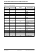
AR1000 SERIES RESISTIVE TOUCH SCREEN CONTROLLER TABLE 9-6: AR1010/AR1020 EEPROM AND REGISTER MAP TABLE 9-7: AR1011/AR1021 EEPROM AND REGISTER MAP EEPROM Address Function EEPROM Address Function 0x20 Calibration LR Y-high 0x1D Calibration UR Y-low 0x21 Calibration LL X-low 0x1E Calibration UR Y-high 0x22 Calibration LL X-high 0x1F Calibration LR X-low 0x23 Calibration LL Y-low 0x20 Calibration LR X-high 0x24 Calibration LL Y-high 0x21 Calibration LR Y-low 0x25 Calibration Flip St
AR1000 SERIES RESISTIVE TOUCH SCREEN CONTROLLER NOTES: DS41393B-page 44 Preliminary 2009-2012 Microchip Technology Inc.
AR1000 SERIES RESISTIVE TOUCH SCREEN CONTROLLER 10.0 APPLICATION NOTES 5. 10.1 Calibration of Touch Sensor with Controller Send:<0x55><0x05><0x21><0x00><0x2E><0x01 ><0x19> The reported coordinates from a touch screen controller are typically calibrated to the application’s video display. The task is often left up to the host to perform. This controller provides a feature for it to send coordinates that have already been calibrated, rather than the host needing to perform this task.
AR1000 SERIES RESISTIVE TOUCH SCREEN CONTROLLER 11. Software must display the third calibration point target in the lower right quadrant of the display and prompt the user to touch and release the target. FIGURE 10-3: SUGGESTED TEXT FOR THIRD CALIBRATION TARGET Touch and Release Target 14. Wait for the user to touch and release the fourth calibration point target. Do this by looking for a controller response of: <0x55><0x02><0x00><0x14> 15.
AR1000 SERIES RESISTIVE TOUCH SCREEN CONTROLLER 10.2 AR1011/AR1021 Storing Default Calibration Values to EEPROM An example of calculating the checksum is shown below (See Table 10-1). If you wish to implement fixed calibration values, pre-loaded into the AR1000 EEPROM, then the following procedure must be followed (See Section 10.2.1 “Preparation for Fixed Calibration Values”). 10.2.
AR1000 SERIES RESISTIVE TOUCH SCREEN CONTROLLER 10.2.2 EXECUTION OF FIXED CALIBRATION VALUE LOADING Follow error checking practices by checking the AR1000 responses to issued commands. 1. 2. 3. 4. Send the AR1000 DISABLE_TOUCH command. Use the AR1000 EEPROM_WRITE command multiple times to write the following to the AR1000 EEPROM. a. Block Key 0x55 to address 0x16 b. Data set to addresses 0x17:0x27. See Section 9.3.4.3 “Calibration Data Encoded and Stored in EEPROM” and Section 9.3.12 “EEPROM Map”. c.
AR1000 SERIES RESISTIVE TOUCH SCREEN CONTROLLER 1. 2. 3. 4. 5. Send the DISABLE_TOUCH (0x13) command. Send the REGISTER_START_ADDRESS_REQUEST (0x22) to determine the absolute address for TouchOptions Register. Send the REGISTER_WRITE (0x21) command to set the CCE bit of the TouchOptions Register. Send REGISTERS_WRITE_TO_EEPROM (0x23) command to have all current registers stored into EEPROM. Send the AR1000 ENABLE_TOUCH (0x12) command.
AR1000 SERIES RESISTIVE TOUCH SCREEN CONTROLLER Disable Touch Command: 55 01 13 Response: 55 02 00 13 Write Calibration to EEPROM Image # 1 Command: 55 0C 29 00 Response: 55 02 00 29 Command: 55 0C 29 00 Response: 55 02 00 29 Command: 55 07 29 00 Response: 55 02 00 29 16 08 55 ULxL ULxH ULyL ULyH URxL URxH URyL 1E 08 URyH LRxL LRxH LRyL LRyH LLxL 26 03 LLyH FlipS Chksm 3E 08 55 ULxL ULxH ULyL ULyH URxL URxH URyL 46 08 URyH LRxL LRxH LRyL LR
AR1000 SERIES RESISTIVE TOUCH SCREEN CONTROLLER 11.0 ELECTRICAL SPECIFICATIONS Absolute Maximum Ratings(†) Ambient temperature under bias....................................................................................................... -40°C to +125°C Storage temperature ........................................................................................................................ -65°C to +150°C Voltage on VDD with respect to VSS .............................................................
AR1000 SERIES RESISTIVE TOUCH SCREEN CONTROLLER 11.1 Minimum Operating Voltage The AR1000 series controller will operate down to 2.5V ± 5%. Touch performance will be optimized by using the highest allowable voltage for the design. The PICkit Serial included in the AR1000 Development kit supports 3V-5V range of operation. 11.2 AR1000 Electrical Characteristics Operating Voltage: 2.5 ≤ VDD ≤ 5.25V Function Pin Input M1 M1 VSS ≤ VIL ≤ 0.15*VDD (0.25*VDD + 0.9V) ≤ VIH ≤ VDD — M2 M2 VSS ≤ VIL ≤ 0.
AR1000 SERIES RESISTIVE TOUCH SCREEN CONTROLLER 12.0 PACKAGING INFORMATION 12.1 Package Marking Information 20-Lead SSOP (5.30 mm) Example AR1021 I/SS e3 1042256 20-Lead SOIC (7.50 mm) Example XXXXXXXXXXXX XXXXXXXXXXXX XXXXXXXXXXXX AR1021 I/SO e3 YYWWNNN Legend: XX...
AR1000 SERIES RESISTIVE TOUCH SCREEN CONTROLLER 12.2 Package Marking Information (Continued) 20-Lead QFN (4x4x0.9 mm) PIN 1 PIN 1 Legend: XX...X Y YY WW NNN e3 * Note: * Example AR1021 I/ML e3 1042256 Customer-specific information Year code (last digit of calendar year) Year code (last 2 digits of calendar year) Week code (week of January 1 is week ‘01’) Alphanumeric traceability code Pb-free JEDEC designator for Matte Tin (Sn) This package is Pb-free.
AR1000 SERIES RESISTIVE TOUCH SCREEN CONTROLLER 12.3 Note: Ordering The AR1011/AR1021 are recommended for new designs. The AR1010/AR1020 are still supported and available, but are not recommended for new designs. TABLE 12-1: ORDERING PART NUMBERS Communication Type Temp.
AR1000 SERIES RESISTIVE TOUCH SCREEN CONTROLLER 12.4 Package Details The following sections give the technical details of the packages.
AR1000 SERIES RESISTIVE TOUCH SCREEN CONTROLLER Note: For the most current package drawings, please see the Microchip Packaging Specification located at http://www.microchip.com/packaging 2009-2012 Microchip Technology Inc.
AR1000 SERIES RESISTIVE TOUCH SCREEN CONTROLLER Note: For the most current package drawings, please see the Microchip Packaging Specification located at http://www.microchip.com/packaging DS41393B-page 58 Preliminary 2009-2012 Microchip Technology Inc.
AR1000 SERIES RESISTIVE TOUCH SCREEN CONTROLLER Note: For the most current package drawings, please see the Microchip Packaging Specification located at http://www.microchip.com/packaging 2009-2012 Microchip Technology Inc.
AR1000 SERIES RESISTIVE TOUCH SCREEN CONTROLLER Note: For the most current package drawings, please see the Microchip Packaging Specification located at http://www.microchip.com/packaging DS41393B-page 60 Preliminary 2009-2012 Microchip Technology Inc.
AR1000 SERIES RESISTIVE TOUCH SCREEN CONTROLLER /HDG 3ODVWLF 4XDG )ODW 1R /HDG 3DFNDJH 0/ ± [ [ PP %RG\ >4)1@ 1RWH )RU WKH PRVW FXUUHQW SDFNDJH GUDZLQJV SOHDVH VHH WKH 0LFURFKLS 3DFNDJLQJ 6SHFLILFDWLRQ ORFDWHG DW KWWS ZZZ PLFURFKLS FRP SDFNDJLQJ D D2 EXPOSED PAD e E2 2 E b 2 1 1 K N N NOTE 1 TOP VIEW L BOTTOM VIEW A A1 A3 8QLWV 'LPHQVLRQ /LPLWV 1XPEHU RI 3LQV 0,//,0(7(56 0,1 1 120 0$; 3LWFK H 2YHUDOO +HLJKW $ 6WDQGRII $ &
AR1000 SERIES RESISTIVE TOUCH SCREEN CONTROLLER 1RWH )RU WKH PRVW FXUUHQW SDFNDJH GUDZLQJV SOHDVH VHH WKH 0LFURFKLS 3DFNDJLQJ 6SHFLILFDWLRQ ORFDWHG DW KWWS ZZZ PLFURFKLS FRP SDFNDJLQJ DS41393B-page 62 Preliminary 2009-2012 Microchip Technology Inc.
AR1000 SERIES RESISTIVE TOUCH SCREEN CONTROLLER APPENDIX A: DATA SHEET REVISION HISTORY Revision A (07/2009) Original release of this data sheet. Revision B (03/2012) Updated data sheet. 2009-2012 Microchip Technology Inc.
AR1000 SERIES RESISTIVE TOUCH SCREEN CONTROLLER APPENDIX B: Modifying, removing or adding components may adversely affect touch performance. Specific manufacturers and part numbers are provided only as a guide. Equivalents can be used. TABLE B-1: Label BILL OF MATERIALS Quantity Value Description Manufacturer C1 1 10 uF Capacitor – Ceramic, 10 uF, 20%, 6.3V, X7R, 0603 AVX 06036D106MAT2A C2 1 0.1 uF Capacitor – Ceramic, 0.
AR1000 SERIES RESISTIVE TOUCH SCREEN CONTROLLER INDEX Numerics P 4, 5, 8-Wire Sensor Selection ............................................. 12 4-Wire Sensor ....................................................................... 7 4-Wire Touch Sensor Interface ........................................... 12 4-Wire Touch Sensor Interface ........................................... 12 5-Wire Sensor ..................................................................... 10 5-Wire Touch Sensor Interface .......
AR1000 SERIES RESISTIVE TOUCH SCREEN CONTROLLER NOTES: DS41393B-page 66 Preliminary 2009-2012 Microchip Technology Inc.
AR1000 SERIES RESISTIVE TOUCH SCREEN CONTROLLER THE MICROCHIP WEB SITE CUSTOMER SUPPORT Microchip provides online support via our WWW site at www.microchip.com. This web site is used as a means to make files and information easily available to customers.
AR1000 SERIES RESISTIVE TOUCH SCREEN CONTROLLER READER RESPONSE It is our intention to provide you with the best documentation possible to ensure successful use of your Microchip product. If you wish to provide your comments on organization, clarity, subject matter, and ways in which our documentation can better serve you, please FAX your comments to the Technical Publications Manager at (480) 792-4150.
AR1000 SERIES RESISTIVE TOUCH SCREEN CONTROLLER NOTES: 2009-2012 Microchip Technology Inc.
Worldwide Sales and Service AMERICAS ASIA/PACIFIC ASIA/PACIFIC EUROPE Corporate Office 2355 West Chandler Blvd. Chandler, AZ 85224-6199 Tel: 480-792-7200 Fax: 480-792-7277 Technical Support: http://www.microchip.com/ support Web Address: www.microchip.