
Datasheet


2009-2012 Microchip Technology Inc. Preliminary DS41393B-page 21
AR1000 SERIES RESISTIVE TOUCH SCREEN CONTROLLER
5.0 SPI COMMUNICATIONS
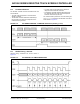
SPI operates in Slave mode with an Idle low SCK and
data transmitted on the SCK falling edge.
5.1 SPI Hardware Interface
A summary of the hardware interface pins is shown
below in Table 5- 1 .
SCK Pin
• The AR1021 controller’s SCL/SCK/TX pin
receives Serial Clock (SCK), controlled by the
host.
• The Idle state of the SCK should be low.
• Data is transmitted on the falling edge of SCK.
SDI Pin
• The AR1021 controller’s SDI/SDA/RX pin reads
Serial Data Input (SDI), sent by the host.
SDO Pin
• The AR1021 controller’s SDO pin presents Serial
Data Output (SDO) to the host.
SIQ Pin
• The AR1021 controller’s SIQ pin provides an
optional interrupt output from the controller to the
host.
• The SIQ pin is asserted high when the controller
has data available (a touch report or a command
response) for the host.
• The SIQ pin is deasserted after the host clocks
out the first byte of the data packet.
SS Pin
• The AR1021 controller’s SS pin provides optional
“slave select” functionality.
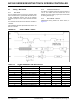
In the ‘inactive’ state, the controller’s SDO pin presents
a high-impedance in order to prevent bus contention
with another device on the SPI bus.
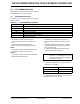
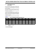
TABLE 5-1: SPI HARDWARE INTERFACE
AR1021 Pin Description
M1 Connect to V
DD to select SPI communications
SDI Serial data sent from master
SCK Serial clock to master
SDO Serial data to master SPI
SIQ
Interrupt output to master (optional)
SS
Slave Select (optional)
Note: The AR1000 Development kit PICkit™
Serial Pin 1 is designated for the SIQ
interrupt pin after the firmware updated is
executed for the PICkit.
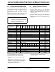
SS Pin Level AR1021 Select
VSS
Active
VDD
Inactive