
Datasheet


52
AT32UC3A
Note: 1. hold length = total cycle duration - setup duration - pulse duration. “hold length” is for “ncs wr hold length” or “nwe hold
length"
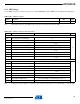
Table 12-24. SMC Read Signals with no Hold Settings
Symbol Parameter Min Units
NRD Controlled (READ_MODE = 1)
SMC
19
Data Setup before NRD High
13.7
ns
SMC
20
Data Hold after NRD High
1
NRD Controlled (READ_MODE = 0)
SMC
21
Data Setup before NCS High
13.3
ns
SMC
22
Data Hold after NCS High
0
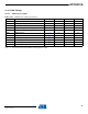
Table 12-25. SMC Write Signals with Hold Settings
Symbol Parameter Min Units
NRD Controlled (READ_MODE = 1)
SMC
23
Data Out Valid before NWE High (nwe pulse length - 1) * t
CPSMC
- 0.9
ns
SMC
24
Data Out Valid after NWE High
(1)
nwe hold length * t
CPSMC
- 6
SMC
25
NWE High to NBS0/A0 Change
(1)
nwe hold length * t
CPSMC
- 1.9
SMC
26
NWE High to NBS1 Change
(1)
nwe hold length * t
CPSMC
- 1.9
SMC
29
NWE High to NBS2/A1 Change
(1)
nwe hold length * t
CPSMC
- 1.9
SMC
30
NWE High to NBS3 Change
(1)
nwe hold length * t
CPSMC
- 1.9
SMC
31
NWE High to A2 - A25 Change
(1)
nwe hold length * t
CPSMC
- 1.7
SMC
32
NWE High to NCS Inactive
(1)
(nwe hold length - ncs wr hold length)* t
CPSMC
- 2.9
SMC
33
NWE Pulse Width nwe pulse length * t
CPSMC
- 0.9
NRD Controlled (READ_MODE = 0)
SMC
34
Data Out Valid before NCS High (ncs wr pulse length - 1)* t
CPSMC
- 4.6
nsSMC
35
Data Out Valid after NCS High
(1)
ncs wr hold length * t
CPSMC
- 5.8
SMC
36
NCS High to NWE Inactive
(1)
(ncs wr hold length - nwe hold length)* t
CPSMC
- 0.6
32058KS–AVR32–01/12