
Datasheet


27
AT32UC3A
10.3 Interrupt Request Signal Map
The various modules may output Interrupt request signals. These signals are routed to the Inter-
rupt Controller (INTC), described in a later chapter. The Interrupt Controller supports up to 64
groups of interrupt requests. Each group can have up to 32 interrupt request signals. All interrupt
signals in the same group share the same autovector address and priority level. Refer to the
documentation for the individual submodules for a description of the semantics of the different
interrupt requests.
The interrupt request signals are connected to the INTC as follows.
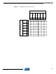
3 Output Driver Enable Register (ODER) WRITE 0x4000_0340 Write-only
SET 0x4000_0344 Write-only
CLEAR 0x4000_0348 Write-only
TOGGLE 0x4000_034C Write-only
Output Value Register (OVR) WRITE 0x4000_0350 Write-only
SET 0x4000_0354 Write-only
CLEAR 0x4000_0358 Write-only
TOGGLE 0x4000_035C Write-only
Pin Value Register (PVR) - 0x4000_0360 Read-only
Table 10-2. Local bus mapped GPIO registers
Port Register Mode
Local Bus
Address Access
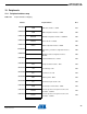
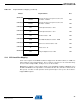
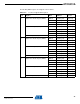
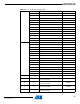
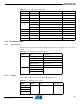
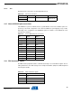
Table 10-3. Interrupt Request Signal Map
Group Line Module Signal
00
AVR32 UC CPU with optional MPU and
optional OCD
SYSBLOCK
COMPARE
1
0 External Interrupt Controller EIC 0
1 External Interrupt Controller EIC 1
2 External Interrupt Controller EIC 2
3 External Interrupt Controller EIC 3
4 External Interrupt Controller EIC 4
5 External Interrupt Controller EIC 5
6 External Interrupt Controller EIC 6
7 External Interrupt Controller EIC 7
8 Real Time Counter RTC
9 Power Manager PM
10 Frequency Meter FREQM
32058KS–AVR32–01/12