
Datasheet

45
AT32UC3A
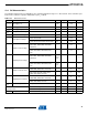
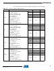
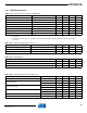
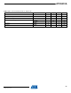
These figures represent the power consumption measured on the power supplies.
Table 12-9. Power Consumption for Different Modes
Mode Conditions Typ. Unit
Active
Typ : Ta =25 °C
CPU running from flash
(1)
.
VDDIN=3.3 V. VDDCORE =1.8V.
CPU clocked from PLL0 at f MHz
Voltage regulator is on.
XIN0 : external clock.
(1)
XIN1 stopped. XIN32 stopped
PLL0 running
All peripheral clocks activated.
GPIOs on internal pull-up.
JTAG unconnected with ext pull-up.
f = 12 MHz 9 mA
f = 24 MHz 15 mA
f = 36MHz 20 mA
f = 50 MHz 28 mA
f = 66 MHz 36.3 mA
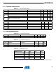
Idle
Typ : Ta = 25 °C
CPU running from flash
(1)
.
VDDIN=3.3 V. VDDCORE =1.8V.
CPU clocked from PLL0 at f MHz
Voltage regulator is on.
XIN0 : external clock.
XIN1 stopped. XIN32 stopped
PLL0 running
All peripheral clocks activated.
GPIOs on internal pull-up.
JTAG unconnected with ext pull-up.
f = 12 MHz 5 mA
f = 24 MHz 10 mA
f = 36MHz 14 mA
f = 50 MHz 19 mA
f = 66 MHz 25.5 mA
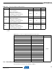
Frozen
Typ : Ta = 25 °C
CPU running from flash
(1)
.
CPU clocked from PLL0 at f MHz
Voltage regulator is on.
XIN0 : external clock.
XIN1 stopped. XIN32 stopped
PLL0 running
All peripheral clocks activated.
GPIOs on internal pull-up.
JTAG unconnected with ext pull-up.
f = 12 MHz 3 mA
f = 24 MHz 6 mA
f = 36MHz 9 mA
f = 50 MHz 13 mA
f = 66 MHz 16.8 mA
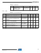
Standby
Typ : Ta = 25 °C
CPU running from flash
(1)
.
CPU clocked from PLL0 at f MHz
Voltage regulator is on.
XIN0 : external clock.
XIN1 stopped. XIN32 stopped
PLL0 running
All peripheral clocks activated.
GPIOs on internal pull-up.
JTAG unconnected with ext pull-up.
f = 12 MHz 1 mA
f = 24 MHz 2 mA
f = 36MHz 3 mA
f = 50 MHz 4 mA
f = 66 MHz 4.8 mA
32058KS–AVR32–01/12