
Datasheet


43
AT32UC3A
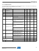
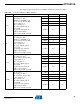
Table 12-7. BOD Timing
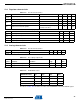
12.4.2 POR
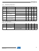
Table 12-8. Electrical Characteristic
Symbol Parameter Test Conditions Typ. Max. Units.
T
BOD
Minimum time with
VDDCORE < VBOD to
detect power failure
Falling VDDCORE
from 1.8V to 1.1V
300 800 ns
Symbol Parameter Test Conditions Min. Typ. Max. Units.
V
DDRR
VDDCORE rise rate to ensure power-on-reset 0.01 V/ms
V
SSFR
VDDCORE fall rate to ensure power-on-reset 0.01 400 V/ms
V
POR+
Rising threshold voltage: voltage up to which
device is kept under reset by POR on rising
VDDCORE
Rising VDDCORE:
V
RESTART
-> V
POR+
1.35 1.5 1.6 V
V
POR-
Falling threshold voltage: voltage when POR
resets device on falling VDDCORE
Falling VDDCORE:
1.8V -> V
POR+
1.25 1.3 1.4 V
V
RESTART
On falling VDDCORE, voltage must go down to
this value before supply can rise again to ensure
reset signal is released at
V
POR+
Falling VDDCORE:
1.8V -> V
RESTART
-0.1 0.5 V
T
POR
Minimum time with VDDCORE < V
POR-
Falling VDDCORE:
1.8V -> 1.1V
15 us
T
RST
Time for reset signal to be propagated to system 200 400 us
32058KS–AVR32–01/12