
Datasheet


64
AT32UC3A
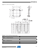
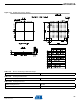
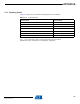
13. Mechanical Characteristics
13.1 Thermal Considerations
13.1.1 Thermal Data
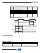
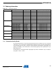
Table 13-1 summarizes the thermal resistance data depending on the package.
13.1.2 Junction Temperature
The average chip-junction temperature, T
J
, in °C can be obtained from the following:
1.
2.
where:
• θ
JA
= package thermal resistance, Junction-to-ambient (°C/W), provided in Table 13-1 on page
64.
• θ
JC
= package thermal resistance, Junction-to-case thermal resistance (°C/W), provided in
Table 13-1 on page 64.
• θ
HEAT SINK
= cooling device thermal resistance (°C/W), provided in the device datasheet.
•P
D
= device power consumption (W) estimated from data provided in the section ”Power
Consumption” on page 44.
•T
A
= ambient temperature (°C).
From the first equation, the user can derive the estimated lifetime of the chip and decide if a
cooling device is necessary or not. If a cooling device is to be fitted on the chip, the second
equation should be used to compute the resulting average chip-junction temperature T
J
in °C.
Table 13-1. Thermal Resistance Data
Symbol Parameter Condition Package Typ Unit
θ
JA
Junction-to-ambient thermal resistance Still Air TQFP100 43.4
⋅C/W
θ
JC
Junction-to-case thermal resistance TQFP100 5.5
θ
JA
Junction-to-ambient thermal resistance Still Air LQFP144 39.8
⋅C/W
θ
JC
Junction-to-case thermal resistance LQFP144 8.9
T
J
T
A
P
D
θ
JA
×()+=
T
J
T
A
P(
D
θ(
HEATSINK
×θ
JC
))++=
32058KS–AVR32–01/12